


Appendix - 36
MELSEC-Q
APPENDICES
Appendix4.2 Wiring of manual pulse generator cable
There are no our option in the manual pulse generator. The manual pulse generator
cable fabricate on the customer side.
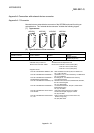
(1) Manual pulse generator cable
The following table indicates the manual pulse generator cables used with motion
controller and the manual pulse generator. Make selection according to your
operating conditions.
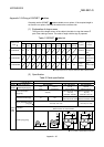
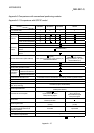
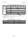
Table 1 Table of wire specifications
Characteristics of one core
Wire model
Core
size
[mm
2
]
Number of
cores
Structure
[Number of
wires/mm]
Conductor
resistance
[
/km]
Insulating
sheath OD
d[mm]
(Note-1)
Finish OD
[mm]
(Note-2)
17/0.16-6P-SRV-SV(2464)K 0.3 12(6 pairs) 17/0.16 Max. 57.5 1.26 8.4
NFKEV-SB 0.3 mm
2
4P 0.3 8(4 pairs)
7/0.127 Max. 66.3
1.30 7.6
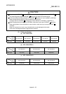
(Note-1): d is as shown below.
Insulation sheath
Conductor
d
(Note-2): Standard OD. Max. OD is about 10% larger.
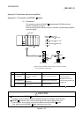
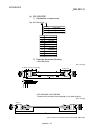
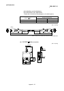
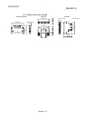
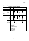
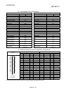
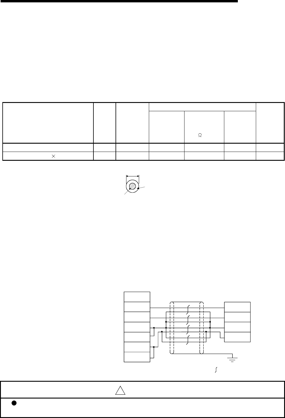
(a) Connection diagram
When fabricating a cable, use the recommended wire given on (1), and
make the cable as show in the following connection diagram. The overall
distance of the manual pulse generator cable on the same bus is
30m(98.4ft.) .
(Note): Connect the shield to ground only on the manual pulse generator
side. (Only one side is connected.)
QD75MH
Manual pulse
generator
Shield
A
phase
Pin No.
1B19
1B20
1B15
A
B
5V
0V
1A15
:Twisted pair cable
5V
1B14
1A14
0V
B phase
!
CAUTION
When fabricating the cable, do not make incorrect connection. Wrong connection will cause runaway or
explosion.