


5 - 86
MELSEC-Q
5 DATA USED FOR POSITIONING CONTROL
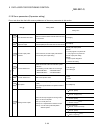
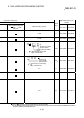
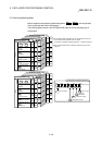
5.2.10 Servo parameters (Input/output setting)
Do not set other than the buffer memory addresses of the servo parameters in this section.
Item
2
Setting details
Setting value
00: Always OFF
01: Maker setting
(Note-3)
02: RD (Servo ON)
03: ALM (Servo alarm)
04: INP (In-position)
(Note-1)
05: MBR (Electromagnetic brake
interlock)
06: DB (Dynamic brake)
07: TLC (Limiting torque)
08: WNG (Servo warning)
09: BWNG (Battery warning)
0A: Always OFF
(Note-2)
0B: Maker setting
(Note-3)
0C: ZSP (Zero speed)
0D: Maker setting
(Note-3)
0E: Maker setting
(Note-3)
0F: CDPS (Variable gain
selection)
10: Maker setting
(Note-3)
11: ABSV (Absolute position
erasing)
(Note-1)
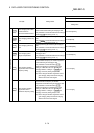
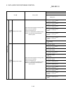
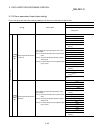
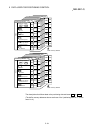
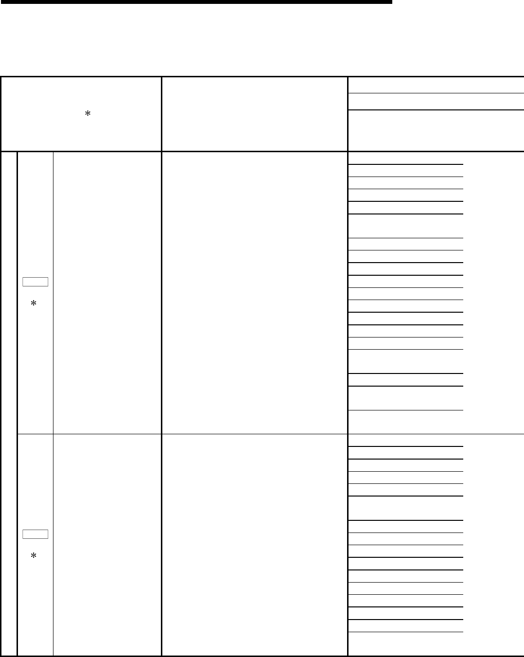
Pr.202
(PD07)
3
Output signal device selection
1(CN3-13)
Used to select the output signal (CN3-13 pin) of the
servo amplifier.
(Note-1): It becomes to always OFF in speed control
mode.
(Note-2): It becomes SA (Speed reached) in speed
control mode.
(Note-3): For maker setting do not changed this value
by any means.
12 to 1F, 20 to 3F: Maker setting
(Note-3)
00: Always OFF
01: Maker setting
(Note-3)
02: RD (Servo ON)
03: ALM (Servo alarm)
04: INP (In-position)
(Note-1)
05: MBR (Electromagnetic brake
interlock)
06: DB (Dynamic brake)
07: TLC (Limiting torque)
08: WNG (Servo warning)
09: BWNG (Battery warning)
0A: Always OFF
(Note-2)
0B: Maker setting
(Note-3)
0C: ZSP (Zero speed)
0D: Maker setting
(Note-3)
0E: Maker setting
(Note-3)
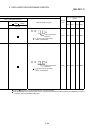
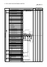
Input/output setting
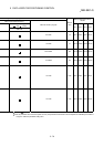
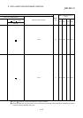
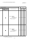
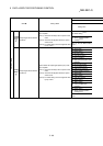
Pr.203
(PD08)
3
Output signal device selection
2(CN3-9)
Used to select the output signal (CN3-9 pin) of the
servo amplifier.
(Note-1): It becomes to always OFF in speed control
mode.
(Note-2): It becomes SA (Speed reached) in speed
control mode.
(Note-3): For maker setting do not changed this value
by any means.
0F: CDPS (Variable gain
selection)