


4 - 2
MELSEC-Q
4 INSTALLATION, WIRING AND MAINTENANCE OF THE PRODUCT
4.1 Outline of installation, wiring and maintenance
4.1.1 Installation, wiring and maintenance procedures
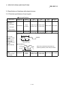
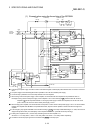
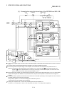
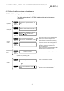
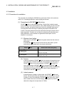
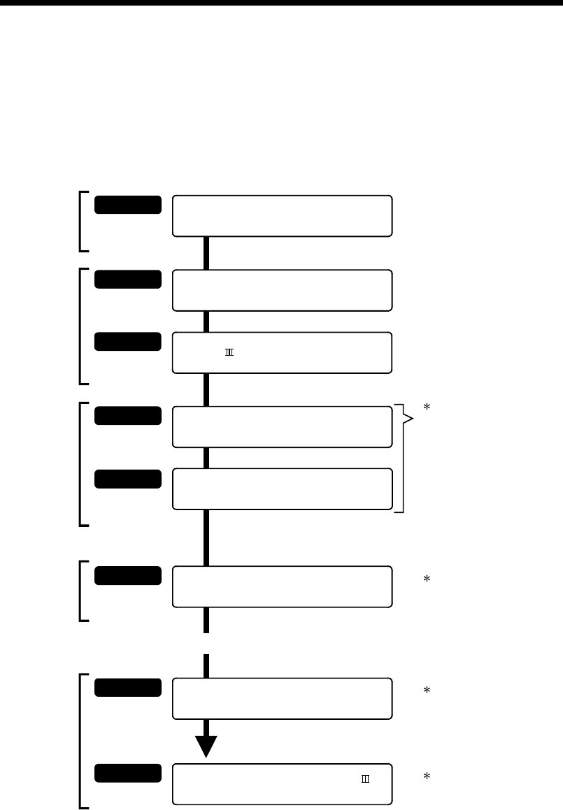
The outline and procedures for QD75MH installation, wiring and maintenance are
shown below.
Dispose of the QD75MH and SSCNET
cable
STEP 1
STEP 2
STEP 4
STEP 5
STEP 6
STEP 7
STEP 8
Refer to
Section 4.5
Refer to
Section 4.5
Refer to
Section 4.3
Refer to
Section 4.3
Refer to
Section 4.2
Refer to
Section 4.1
Preparation
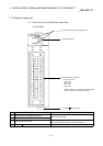
Understand the "Handling precautions" and
"Names of each part" of the module (QD75
MH)
Installing the
module
Install the module (QD75MH) on the base unit.
Wiring the
module
Wire the external device connection
connector pins, and assemble the connector.
Connect the cable to the module (QD75MH)
Wire and connect the manufactured cable to QD75
MH after reading the precautions for wiring.
Confirmin
g
the
installation and
w
irin
g
Servicing the
module
Confirm the connection
Check the connection using GX Configurator-QP.
Operation of the positioning system.
Carry out maintenance
Carry out maintenance as necessary.
When the QD75MH is no longer necessary,
dispose of it with the specified methods.
Refer to
Section 4.4
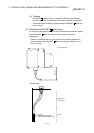
The cables used to connect the QD75MH with the
drive unit, with the mechanical system input
(each input/output signal), and with the manual
pulse generator are manufactured by soldering
each signal wire onto the "external device
connection connector" sold separately.(Refer to
"Applicable connector for external wiring" in
Section 3.1 "Performance specifications" for
the optional connector.)
STEP 3
Refer to
Section 4.2
Understand the "Precautions for wiring of
SSCNET cable" before wiring of the
module (QD75MH).