


5 - 34
MELSEC-Q
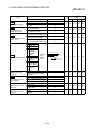
5 DATA USED FOR POSITIONING CONTROL
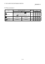
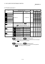
Setting value, setting range
Setting value buffer memory
address
Item
Value set with peripheral device Value set with PLC program
Default
value
Axis 1 Axis 2 Axis 3 Axis 4
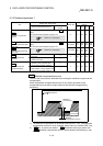
0 : Standard speed switching mode 0
Pr.19
Speed switching mode
1 : Front-loading speed switching
mode
1
0 28 178 328 478
0 : Composite speed 0
Pr.20
Interpolation speed
designation method
1 : Reference axis speed 1
0 29 179 329 479
0 : Do not update current feed value 0
1 : Update current feed value 1
Pr.21
Current feed value during
speed control
2 : Clear current feed value to zero 2
0 30 180 330 480
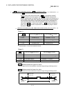
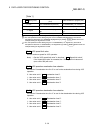
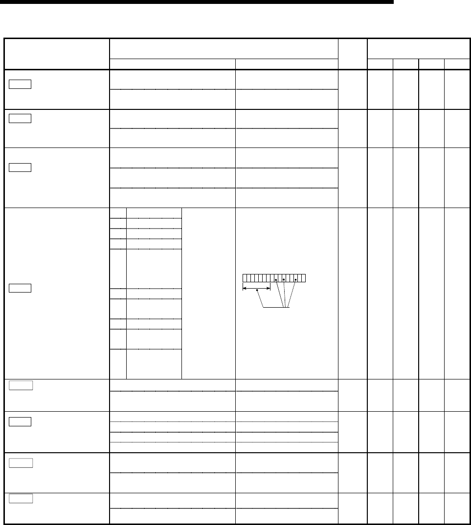
b0 Lower limit
b1 Upper limit
b2 Not used
b3 Stop signal
b4
External
command/
switching
signal
b5 Not used
b6
Near-point dog
signal
b7 Not used
b8
Manual pulse
generator input
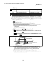
Pr.22
Input signal logic selection
b9
to
b15
Not used
0: Negative
logic
1: Positive
logic
b0123456789101112131415
Always "0" is set to
the
p
art not used.
0 31 181 331 481
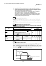
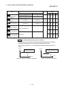
0: External input signal of QD75MH 0
Pr.80
External input signal
selection
1: External input signal of servo
amplifier
1
0 32 182 332 482
0: A-phase/B-phase multiplied by 4 0
1: A-phase/B-phase multiplied by 2 1
2: A-phase/B-phase multiplied by 1 2
Pr.24
Manual pulse generator
input selection
3: PLS/SIGN 3
0 33
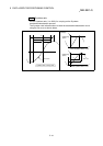
0: Speed-position switching control
(INC mode)
0
Pr.81
Speed-position function
selection
2: Speed-position switching control
(ABS mode)
2
0 34 184 334 484
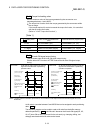
0: Valid 0
Pr.82
Forced stop valid/invalid
selection
1: Invalid 1
0 35