


5 - 33
MELSEC-Q
5 DATA USED FOR POSITIONING CONTROL
Pr.17
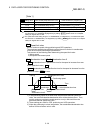
Torque limit setting value
Set the maximum value of the torque generated by the servomotor as a
percentage between 1 and 1000%.
The torque limit function limits the torque generated by the servomotor within
the set range.
If the torque required for control exceeds the torque limit value, it is controlled
with the set torque limit value.
(Refer to "12.4.2 Torque limit function".)
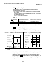
[Table 1]
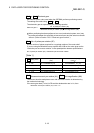
Pr.1
setting value
Value set with peripheral device
(unit)
Value set with PLC program (unit)
0 : mm 0.1 to 214748364.7 (µm)
1 to 2147483647 (×10
–1
µm)
1 : inch 0.00001 to 21474.83647 (inch)
1 to 2147483647 (×10
–5
inch)
2 : degree 0.00001 to 21474.83647 (degree)
1 to 2147483647 (×10
–5
degree)
3 : PLS 1 to 2147483647 (PLS) 1 to 2147483647 (PLS)
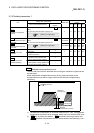
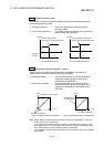
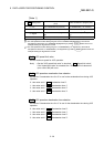
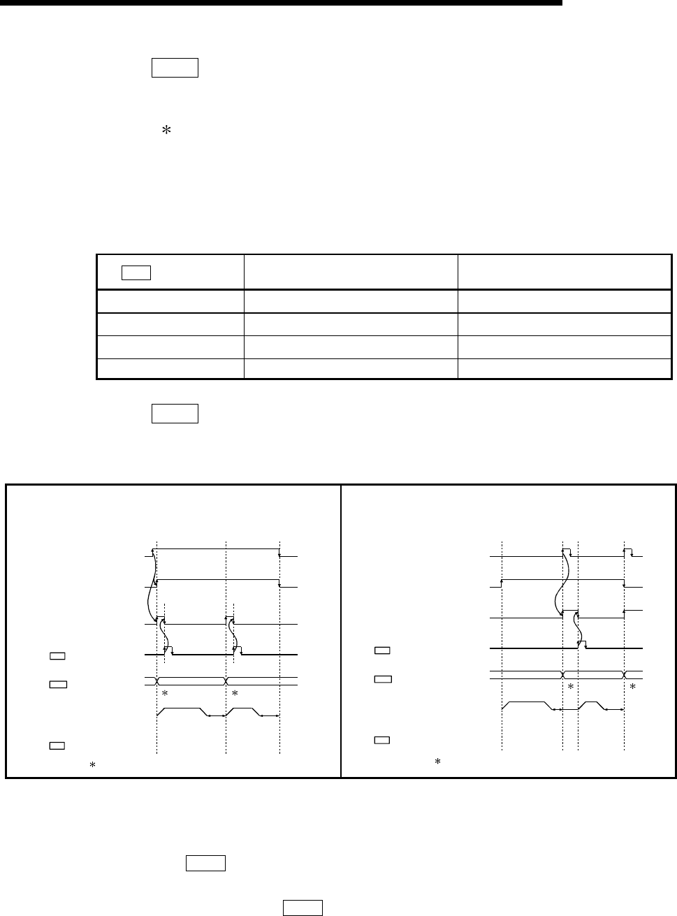
Pr.18
M code ON signal output timing
This parameter sets the M code ON signal output timing.
Choose either WITH mode or AFTER mode as the M code ON signal output
timing.
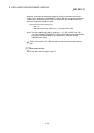
WITH mode......... An M code is output and the M code ON
signal is turned ON when a positioning
operation starts.
m1 m2
01 (continuous) 00 (end)
Positioning start signal
[Y10,Y11,Y12,Y13]
BUSY signal
[XC,XD,XE,XF]
Positioning
M code ON signal
[X4,X5,X6,X7]
M code OFF request
[1504,1604,1704,1804]
Cd.7
Operation pattern
Da.1
Valid M code
Md.25
: m1 and m2 indicate set M codes.
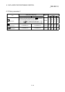
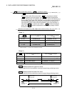
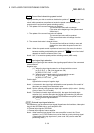
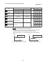
AFTER mode......An M code is output and the M code ON
signal is turned ON when a positioning
operation completes.
: m1 and m2 indicate set M codes.
m1
m2
01 (continuous) 00 (end)
Positioning complete signal
[X14,X15,X16,X17]
BUSY signal
[XC,XD,XE,XF]
Positioning
M code ON signal
[X4,X5,X6,X7]
M code OFF request
[1504,1604,1704,1804]
Cd.7
Operation pattern
Da.1
Valid M code
Md.25
Note: If AFTER mode is used with speed control, an M code will not be output and the M code ON signal will not be
turned ON.
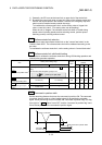
An M code is a number between 0 and 65535 that can be assigned to each positioning
data (
Da.10
).
The sequence program can be coded to read an M code from the buffer memory
address specified by "
Md.25
Valid M code" whenever the M code ON signal [X4, X5,
X6, X7] turns ON so that a command for the sub work (e.g. clamping, drilling, tool
change) associated with the M code can be issued.