


2 - 6
MELSEC-Q
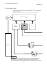
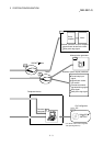
2 SYSTEM CONFIGURATION
2.3 Applicable system
The QD75MH can be used in the following system.
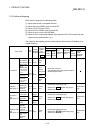
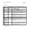
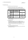
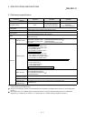
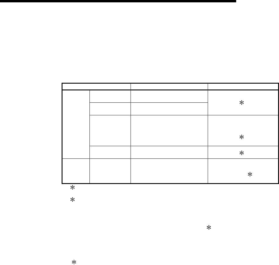
(1) Applicable modules and the number of installable modules
The following table indicates the CPU modules and network modules (for remote
I/O station) usable with the QD75MH and the number of installable modules.
Applicable modules Number of installable modules Remarks
Q00JCPU Max. 8 modules
Q00CPU
Q01CPU
Max. 24 modules
( 1)
Q02CPU
Q02HCPU
Q06HCPU
Q12HCPU
Q25HCPU
Max. 64 modules
Installable in the Q mode
only
(
1)
CPU
module
Q12PHCPU
Q25PHCPU
Max. 64 modules
(
1)
Network
module
QJ72LP25-25
QJ72BR15
QJ72LP25G
QJ72LP25GE
Max. 64 modules
MELSECNET/H remote I/O
station (
2)
1: Refer to the QCPU User's Manual (Hardware Design, Maintenance and Inspection) of
the CPU module used.
2: Refer to the Q Corresponding MELSECNET/H Network System Reference Manual
(Remote I/O Network).
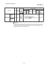
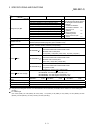
(2) Usable base unit
The QD75MH can be installed in any of the I/O slots (
3
) of a base unit.
When installing the QD75MH, always consider the power supply capacity since a
shortage of the power supply capacity may occur depending on the combination
with the other installed module and the number of installed module.
3: Within the I/O point range of the CPU module and network module (for remote I/O
station).
(3) Compatibility with Multiple PLC system
When using the QD75MH in a Multiple PLC system, first refer to the QCPU User's
Manual (Multiple CPU system).