


1 - 26
MELSEC-Q
1 PRODUCT OUTLINE
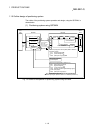
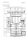
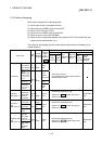
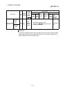
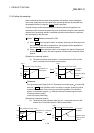
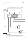
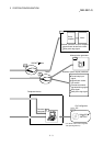
1.2.3 Outline of stopping
Each control is stopped in the following cases.
(1) When each control is completed normally.
(2) When the Servo READY signal is turned OFF.
(3) When a PLC CPU error occurs.
(4) When the PLC READY signal is turned OFF.
(5) When an error occurs in the QD75MH.
(6) When control is intentionally stopped (Stop signal from PLC CPU turned ON, stop
signal from an external device, etc.).
The outline for the stopping process in these cases is shown below. (Excluding (1) for
normal stopping.)
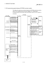
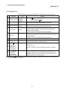
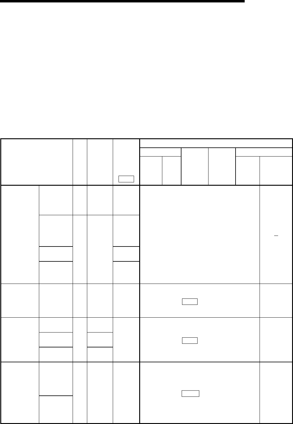
Stop process
OPR control Manual control
Stop cause
Stop
axis
M code
ON signal
after stop
Axis
operation
status
after
stopping
(
Md.26
)
Machine
OPR
control
Fast
OPR
control
Major
positioning
control
High-level
positioning
control
JOG/
Inching
operation
Manual
pulse
generator
operation
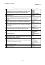
"Forced stop
input signal
from external
device" OFF
All
axes
No
change
Servo
OFF
Servo
READY OFF
• Servo amplifier
power supply
OFF
Servo
amplifier
disconnected
• Servo alarm
During
error
Forced stop
• Forced stop
input to servo
amplifier
Each
axis
No
change
Servo
OFF
Servo OFF or free run
(The operation stops with dynamic brake or
electromagnetic brake.)
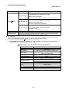
Fatal stop
(Stop group 1)
Hardware
stroke limit
upper/lower
limit error
occurrence
Each
axis
No
change
During
error
Deceleration stop/sudden stop
(Select with "
Pr.37
Sudden stop group1
sudden stop selection" )
Deceleration
stop
Error occurs
in PLC CPU
No
change
PLC READY
signal OFF
Turns
OFF
Emergency
stop
(Stop group 2)
Error in test
mode
All
axes
No
change
During
error
Deceleration stop/sudden stop
(Select with "
Pr.38
Sudden stop group2
sudden stop selection" )
Deceleration
stop
Axis error
detection
(Error other
than stop
group 1 or 2)
Relatively safe
stop
(Stop group 3)
"Stop signal"
from
peripheral
device
Each
axis
No
change
During
error
Deceleration stop/sudden stop
(Select with "
Pr.39 Sudden stop group3
sudden stop selection" )
Deceleration
stop