


5 - 44
MELSEC-Q
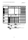
5 DATA USED FOR POSITIONING CONTROL
Setting value, setting range
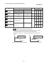
Setting value buffer memory
address
Item
Value set with peripheral device Value set with PLC program
Default
value
Axis 1 Axis 2 Axis 3 Axis 4
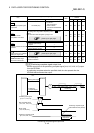
Pr.40
Positioning complete signal
output time
0 to 65535 (ms)
0 to 65535 (ms)
0 to 32767 :
Set as a decimal
32768 to 65535:
Convert into hexadecimal
and set
300 59 209 359 509
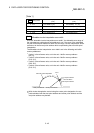
Pr.41
Allowable circular
interpolation error width
The setting value range differs depending on the "
Pr.1
Unit
setting".
Here, the value within the [Table 1] range is set.
[Table 1] on right page
100
60
61
210
211
360
361
510
511
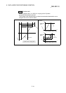
0: External positioning start 0
1: External speed change
request
1
2: Speed-position, position-
speed switching request
2
Pr.42
External command function
selection
3: Skip request 3
0 62 212 362 512
Pr.83
Speed control 10 x multiplier
setting for degree axis
[Table 2] on right page
0 63 213 363 513
Pr.84
Restart allowable range
when servo OFF to ON
0, 1 to 327680 [PLS]
0: restart not allowed
0
64
65
214
215
364
365
514
515
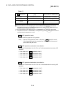
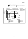
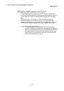
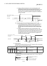
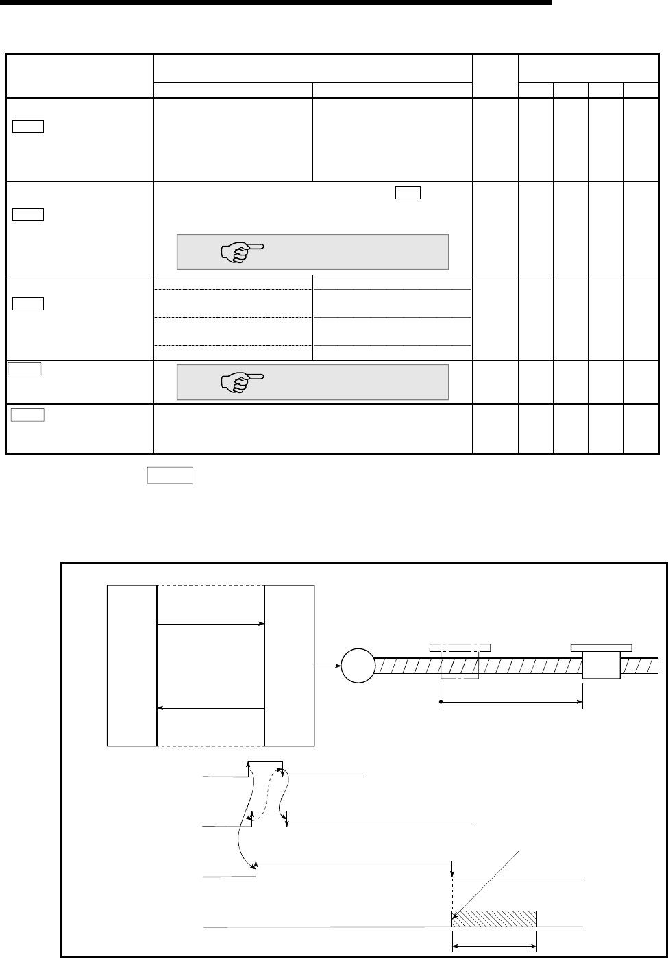
Pr.40 Positioning complete signal output time
Set the output time of the positioning complete signal [X14, X15, X16, X17] output
from the QD75MH.
A positioning completes when the specified dwell time has passed after the
QD75MH had terminated the output.
M
QD75MH
[Y10, Y11, Y12, Y13]
PLC
PLC CPU
Positining Start signal
Positioning
complete signal
[X14, X15, X16, X17]
Positioning
Positioning start signal
Start complete signal
BUSY signal
Positioning complete signal
Positioning complete signal
(after dwell time has passed)
Output time
[Y10, Y11,Y12,Y13]
[X10, X11, X12, X13]
[XC, XD, XE, XF]
[X14, X15, X16, X17]
Positioning complete signal output time