


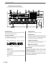
The Controls & Connectors
RS7000 13
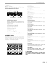
[REAL TIME LOOP REMIX] Button (Page 239)
Turns the real-time loop remix function on or off. The
indicator lights when the real-time remix feature is on.
[SAMPLE EDIT] Button (Page 241)
Engages the SAMPLE EDIT mode. The indicator lights
when the SAMPLE EDIT mode is active.
[STANDBY START/STOP] Button (Page 229)
Switches to the sampling mode, and starts/stops the sam-
pling operation.
[REC VOLUME] Control
Adjusts the input level of the analog signal appearing at
the INPUT L and R connectors. Used for sample recording
and A/D input.
When the optional AIEB2 I/O expansion board is installed,
additional DIGITAL IN and OPTICAL IN inputs are avail-
able, but the [REC VOLUME] control does not affect the
input level of these inputs.
3
MIDI IN/OUT Indicator
The appropriate lamp will flash when MIDI data is received
or transmitted by the RS7000. Use this indicator to confirm
MIDI data reception or transmission.
4
[MASTER VOLUME] Control
Adjusts the level of the signal appearing at the RS7000
OUTPUT L/MONO and R connectors as well as the
PHONES jack.
When the optional AIEB2 I/O expansion board is installed,
additional ASSIGNABLE OUT (AS1 ~ 6), DIGITAL OUT,
and OPTICAL OUT outputs are available, but the [MAS-
TER VOLUME] control does not affect the level of these
outputs.
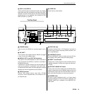
5
Display
This backlit LCD (Liquid Crystal Display) displays all infor-
mation and parameters necessary for operation of the
RS7000.
6
[Knob 1] ~ [Knob 4]
These four knobs adjust the parameter values which
appear directly above them in the display. Rotating a knob
while holding then [SHIFT] button allows coarse adjustment
at approximately 10x the normal rate.
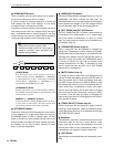
7
[F1] ~ [F4] Function Buttons
Select parameters appearing on the bottom line of the LCD,
execute functions, and switch between display pages.
When more than one parameter is assigned to a single
function knob ([Knob 1] ~ [Knob 4]), the corresponding
function button can be used to select the parameter to be
edited.
When a function knob is active (i.e. it can be used to per-
form a function), the corresponding indicator will light.
When a numeric parameter is to be edited, in some cases
the SUB MODE buttons can be used as a numeric keypad
for direct numeric data entry while the [SHIFT] and related
function button ([F1] ~ [F4]) is held (Page 66).
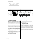
8
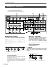
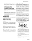
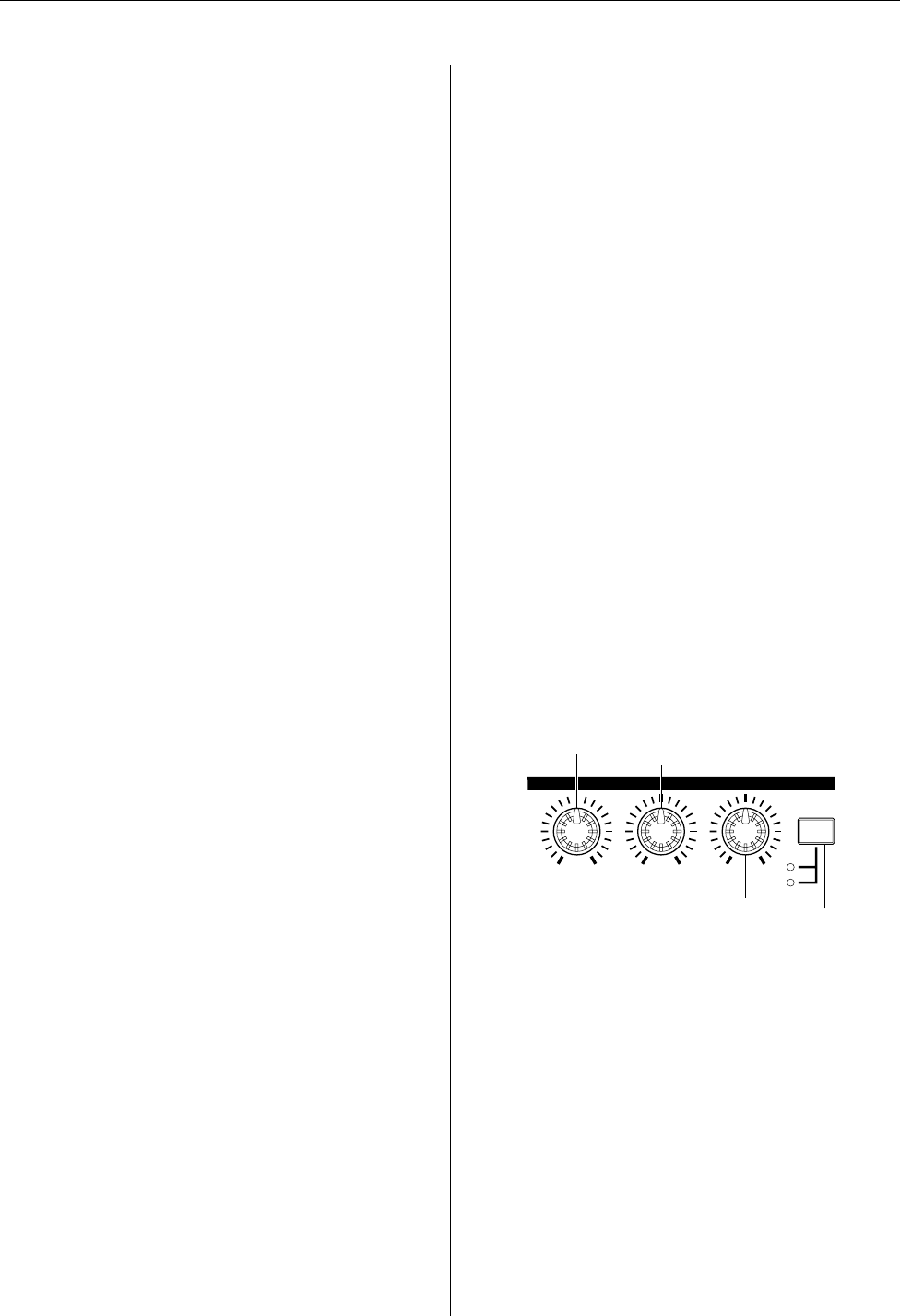
SEQUENCE PLAY FX Controls
In addition to the functions described here, these knobs are
fully assignable and can be set up to control a wide range
of functions and parameters.
Since the knobs allow continuous parameter control for the
selected track, they can be used for creative real-time per-
formance sound control. 2 functions can be assigned to
each knob, selected by the [SELECT] button to their right,
allowing the three knobs to control up to 6 different parame-
ters or functions.
The default assignments for these knobs are the main
PLAY EFFECT and MIDI DELAY parameters. Refer to
“Chapter 2: The Pattern mode”, pages 87 and 90, for more
information on PLAY EFFECTS and MIDI DELAY.
[BEAT STRETCH/GATE TIME] Knob
With the initial default settings, this knob provides real-
time control of the PLAY FX BEAT STRETCH and GATE
TIME parameters.
BEAT STRETCH compresses or expands the length of
measures (Page 89), while GATE TIME alters the gate
time of the notes (Page 88).
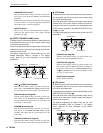
[CLOCK SHIFT/MIDI DELAY] Knob
With the initial default settings, this knob provides real-
time control of the PLAY FX CLOCK SHIFT and MIDI
DELAY parameters.
CLOCK SHIFT shifts the timing of notes (Page 89), while
MIDI DELAY adjusts the delay time of the MIDI DELAY
effect (Page 91).
BEAT STRETCH
GATE TIME
CLOCK SHIFT
MIDI DELAY
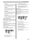
SWING
VELOCITY
SELECT
SEQUENCE PLAY FX
[BEAT STRETCH/GATE TIME] Knob
[CLOCK SHIFT/MIDI DELAY] Knob
[SWING/VELOCITY] Knob
[SELECT] Button