


Product Description
VX4101A MultiPaq Instrument User Manual
1–9
NOTE. If you do not want to use dynamic addressing, align the desired switch
position with the arrow on the module shield.
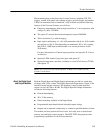
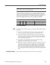
The physical address of the instrument is on a 64 byte boundary. If the Logical
Address switch representing the most significant digit (LA-HI) of the logical
address is set to position X and the switch representing the least significant digit
(LA-LO) of the logical address is set to position Y, then the base physical
address of the module will be [(40
16
× XY
16
) + C000
16
]. For example:
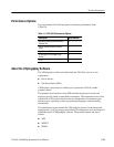
Base Physical Address
L.A. HI LO decimal hexadecimal
A
16
0
16
A
16
(64 * 10) + 49152 = 49792 (40
16
* A
16
) + C000
16
= C280
16
15
16
1
16
5
16
(64 * 21) + 49152 = 50496 (40
16
* 15
16
) + C000
16
= C540
16
L.A. is the Logical Address
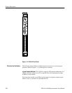
The VX4101A has four LEDs visible on its front panel. These LEDs are labeled
as follows:
H Power LED – this LED is On if all six fuses for the six power buses are
intact. Any single fuse being blown results in the LED turning OFF
H Fail LED – this LED is normally OFF. During power-on or reset self-test,
the LED will be ON for the duration of the test. If the VX4101A detects a
failure during normal operation, the LED will come ON and the SYSFAIL
line on the backplane will be true
H Message LED – this LED flickers ON when the VX4101A is being
addressed on the VME backplane by its commander
H ERR LED – this LED is normally OFF. However, it may blink on and off to
indicate error conditions. The most common reason is a command syntax
error has been detected. Other error conditions that will cause the LED to
blink are discussed elsewhere in this manual. Sending the “SYSTem:ER-
Ror?” query to the instrument will return the cause of the error. When all
errors in the queue have been retrieved, the error LED will return to the OFF
state
Refer to Appendix B:Input/Output Connections for more information.
LEDs
Front Panel Connectors