


Appendix A: Specifications
A–8
VX4101A MultiPaq Instrument User Manual
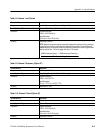
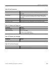
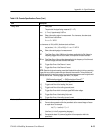
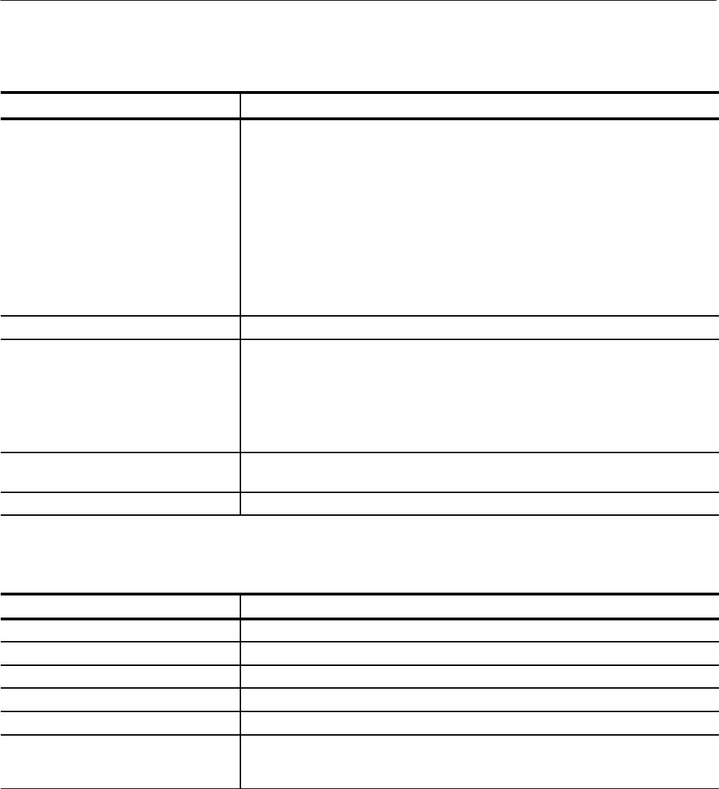
Table A–18: Channels 1 and 2 Input Characteristics (Cont.)
Characteristics Description
Damage Level Input voltage at 1 MW
×1: 300 V (DC or peak AC)
derate to 5 V (DC + peak AC) at 20 dB/decade above 10 kHz
×10: 300 V (DC or peak AC)
derate to 5 V (DC + peak AC) at 20 dB/decade above 10 MHz
×100: 300 V (DC or peak AC)
derate to 5 V (DC + peak AC) at 20 dB/decade above 10 MHz
Input Voltage at 50 W = 5 V (0.5 W) maximum
(Overload protection auto-switch to 1M W over 840 mW (6.5 VDC) in less than 5
seconds.)
Common Input Limitations None
Sensitivity –20 dBm to 200 MHz, then 6 db per octave to
–12 dBm at 500 MHz
–13 dBm at 1000 MHz typical
3dB Low Frequency limit with AC coupling:
1 e6 W input impedance = 10 Hz
50 W input impedance = 200 kHz
Input Channel Noise ±2mV
rms
typt500 mV
rms
Filters None, 20 MHz, or 100 MHz
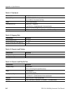
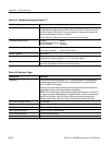
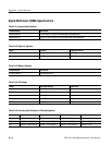
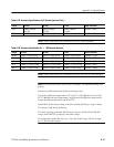
Table A–19: Channel 3 Input Characteristics (Option 2C)
Characteristic Description
Coupling AC
Trigger Slope 3 Positive slope (threshold at mean)
Impedance 3 50 W
Damage Level 3 5 VPTP (AC)
Common Input Limitations t 5 VPP
Sensitivity 3 200 MHz to 1000 MHz–(–30 dBm)
1000 MHz to 3000 MHz–(–25 dBm)
4000 MHz –(–13 dBm typical)