


About Fast Data Channel (FDC) Operation
2–20
VX4101A MultiPaq Instrument User Manual
process varies with the VX4101A configuration and behavior at the time the
OPEN command is issued. To ensure that an opened FDC channel is not used to
transfer data until it is ready to do so, you should poll the FDC channel to
determine if it is ready for data transfers.
The configure query returns the state of the currently selected FDC channel. In
this case, the channel state must be READ_WRITE before data transfer can
reliably commence.
Example Code for Querying the Channel.
while(strncmp(buff,”READ_WRITE”,10))
{
errs = viWrite (wsp, "VXI:FDC:CONF?", 13, &RetCnt);
errs = viRead (wsp, buff, sizeof(buff), &RetCnt);
buff[RetCnt] = 0;
}
After configuring and opening the FDC channel, data transfers can begin. You
can use FDC to quickly and efficiently program an output waveform.
Using ASCII Values. The VX4101A DAC can also be programmed for an output
waveform with easy to use, but slow, ASCII values. When programmed in
ASCII, the DAC converts the ASCII voltage values to binary data prior to
driving its output hardware. When programmed with FDC, the data transferred to
the DAC must already be in a binary format suitable for driving the hardware.
In a typical application, you develop waveform patterns with ASCII data. Then,
using FDC, the instrument reads back the binary representations of the waveform
patterns. During the execution of the production test, the binary representations
of the waveforms can be downloaded to the DAC with FDC. This provides a
mechanism to rapidly and efficiently transmit a variety of different waveforms
from the DAC to the Unit Under Test.
The DAC is specialized for outputting waveforms in real time. In order to read
back its output buffers, you must define the amount of data to return. Reception
of the return count command signals the DAC to present its output data to the
FDC drivers. In the following example code, assume the DAC has already been
programmed with ASCII voltage values. The BUFF command defines the return
count of the data that was read back and the viRead command invokes the host
FDC driver’s read function to retrieve the data via FDC.
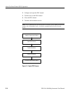
Transferring Data