


Appendix A: Specifications
A–10
VX4101A MultiPaq Instrument User Manual
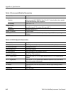
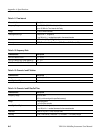
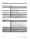
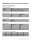
Table A–24: TimeBase Characteristics (Option 1T)
Characteristic Description
Time Base Characteristics The time base can be drawn from four different sources: the on-board 10 MHz source,
the optional on-board high accuracy 10 MHz source, the VXI Slot 0 10 MHz source, and
the Slot 0 External 10 MHz source. The user can select, by programmed command, the
source and what degree of accuracy is required.
The Slot 0 External 10 MHz source can be synchronized to other systems.
Time Base Reference Clock On-board 25 ppm
VXI Slot 0 required accuracy 100 ppm
VXI Slot 0 External As required
Time Base Temperature Stability Standard 25 ppm
High Accuracy (optional) 1.5 ppm (TXCO) Option 1T
External Time Base User provided
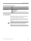
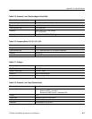
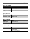
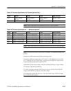
Frequency Range VXI cards are available with tightly controlled specifications, including a Rubidium Vapor
Oscillator with a claimed accuracy of t5 x 10
-11
per month stability.
Interface 10 MHz connected into 50 W Slot 0 connector. The Slot 0 card must be programmed to
source the VXI backplane 10 MHz from the front-panel input.
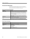
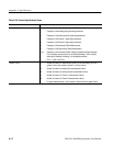
Table A–25: Gate Input Trigger
Characteristic Description
Gate Inputs There are four sources of gate inputs: VXI TTL backplane triggers, on-board processor
generated triggers (either by VXI Command or timer algorithm), front panel Gate/Arm
input, or Channel 2 input as gate.
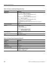
All gate inputs will start and stop counting synchronously with the measured input on its
next transition (Trigger) for all measurements except totalizing.
NOTE: Tektronix terminology uses the measured signals input (Channel 1 or Channel 2)
as Triggers, processor and backplane on/off signals as Gates, and the front-panel control
signal as the Arm signal. When the Channel 2 input signal controls the starting and
stopping of the Channel 1 signal, the Channel 2 signal will be referred to as a Gate.
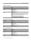
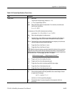
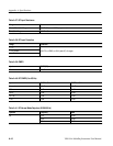
Front Panel Gate Input Interface SMB connector
Polarity Programmable
Gate Type Programmable: level, edge, pulse-on/pulse-off
Edge Triggering Amplitude ±500 mV minimum, ±20 V Maximum
Pulse Width Requirements 40 ns minimum pulse width
Gate Start/End Uncertainty t20 ns