


Reference Voice Mode
Voice Edit mode Normal Voice Edit Common Edit
194
Owner’s Manual
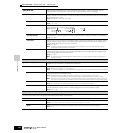
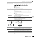
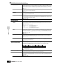
[SF3] PHASE
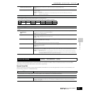
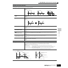
Phase Determines the starting phase point for the LFO Wave when it is reset.
Settings: 0, 90, 120, 180, 240, 270
Offset EL1 - EL4 (Phase Offset
Element1 - Element4)
Determines the offset values of the Phase parameter (above) for the respective Elements.
Settings: +0, +90, +120, +180, +240, +270
[SF4] BOX1 - 3
From this display you can select the destination parameter for the LFO (which aspect of the sound the LFO controls),
the Elements to be affected by the LFO, and the LFO Depth. Three pages (boxes) provided for setting the
destination let you assign multiple destinations.
ElemSw (Element Switch) Determines whether or not each Element is to be affected by the LFO. The Element number (1- 4) is shown when the
LFO is enabled; a dash (-) indicates the LFO is disabled for that Element.
Dest (Destination) Determines the parameters which are to be controlled (modulated) by the LFO Wave.
Settings: amd, pmd, fmd, reso (Resonance), pan, ELFOSpd (Element LFO Speed)
Depth Determines the LFO Wave Depth.
Settings: 0 ~ 127
DptRatio EL1 - EL4 (Depth Offset
Element1 - Element4)
Determines the offset values of the Depth parameter (above) for the respective Elements.
Settings: 0 ~ 127
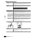
[SF5] USER
This menu is available only when the User LFO wave is selected. You can create a custom LFO wave consisting of
up to sixteen steps.
Template You can select a pre-programmed template for the LFO wave. The selected template's wave graph appears on the
display and you can create the LFO wave by viewing it. Each time pressing the [SF1] random button, different LFO
wave is appears on the display randomly.
Settings:
all0 ...................Values of all the steps are set to 0.
all64 .................Values of all the steps are set to 64.
all127 ...............Values of all the steps are set to 127.
saw up .............Creates a saw shaped upward wave.
saw down.........Creates a saw shaped downward wave.
even step .........Values of all even steps are set to 127, and values of all odd steps are set to 0.
odd step...........Values of all odd steps are set to 127, and values of all even steps are set to 0.
Slope Determines the slope or ramp characteristics of the LFO wave.
Settings: OFF (no slope), up, down, up&down
Value Edits the value for each step.
Settings: 0 ~ 127
Step Selects the step number of the LFO wave.
Settings: 1 ~ 16
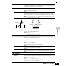
[F6] EFFECT
n For details on the Effect connections in the Voice mode, see page 179. For details on the Effect Types, refer to the Effect Type list in the separate Data List booklet.
[SF1] CONNECT
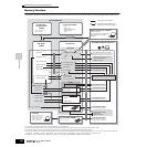
This display gives you comprehensive control over the effects.
EL: OUT 1-4
(Element 1-4 Effect Output)
Determines which Insertion effect (A or B) is used to process each individual Element. The “thru” setting lets you
bypass the Insertion effects for the specific Element.
Settings: insA, insB, thru
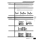
InsEF Connect
(Insertion Effect Connect)
Determines the effect routing for Insertion effects A and B. The setting changes are shown on the diagram in the
display, giving you a clear picture of how the signal is routed.
Settings: Para, InsAtoB, InsBtoA (See page 179.)
InsA Ctgry
(Insertion A Category),
InsA Type (Insertion A Type)
Determines the effect type for Insertion A.
Time
Phase
0° 90°
120° 240°
180° 270°