


Appendix
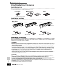
Installing Optional Hardware
284
Owner’s Manual
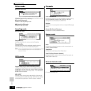
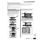
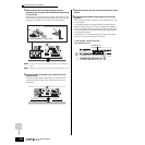
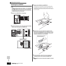
5 With the board still protruding slightly from the
expansion bay, bring the cable end around and connect
it to the board.
Make sure to connect the proper cable, matching the color
of the cable to the slot used. Also, take care not to pull too
strongly on the cable as you connect it to the board.
n The Vocal Harmony Plug-in board (PLG100-VH) can be installed only
to slot 1.
n
The Multi part Plug-in board (PLG-100XG) can be installed only to slot 3.
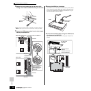
6 Insert the Plug-in board the rest of the way into the
expansion bay.
Carefully put the ribbon cable back into the MOTIF ES,
making sure that no part of the cable sticks out of the
instrument.
7 Replace the cover with the screw you removed in step 2
above.
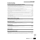
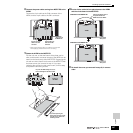
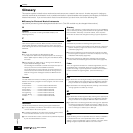
8 Check that the installed Plug-in board is functioning
properly.
After connecting the AC power cord to the MOTIF ES, turn
on the power.
A message appears indicating that the installed Plug-in
Board is being checked. The main display then appears
and the corresponding slot indicator at the right top of the
front panel lights. This indicates that the board has been
successfully installed.
If the cable is not connected properly (refer to the notes
above) or firmly, the indicator will not light.
OUTPUT
ASSIGNABLE
OUTPUT
L MONO
PHONES
A
D
INPUT
GAIN
RL
R
R
L
GREEN
YELLOW
ORANGE
3
2
1
Plug-in SLOT
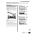
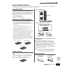
Plug-in Connector Press the connectors together until
the two notches lock into the sockets.
Notch
Connector from MOTIF ES Plug-in board
OUTPUT
ASSIGNABLE
OUTPUT
L MONO
PHONES
A
D
INPUT
GAIN
RL
R
R
L
GREEN
YELLOW
ORANGE
3
2
1
Plug-in SLOT
FAVORITES
DRUM KITS
A. PIANO KEYBOARD ORGAN
PRE 5 PRE 6
PRE 1 PRE 2 PRE 3 PRE 4
MUSIC PRODUCTION SYNTHESIZER
Integrated Sampling Sequencer /
Modular Synthesis Plug-in System /
Real-time External Control Surface
USER 1
GUITAR/
PLUCKED
SYN LEAD
ABCDEFG
H
SECTION
GROUP
CATEGORY
SEARCH
BANK
SYN PAD/
CHOIR
SYN COMP
CHROMATIC
PERCUSSION
DRUM/
PERCUSSION
SE MUSICAL FX COMBI
USER 2
STRINGS
PLG 1
SLOT 1 SLOT 2 SLOT 3
BRASS
PLG 2
REED/PIPE
PLG 3
BASS
GM
Slot indicator lit
In this example, a Plug-in board has
been installed to slot 1.