


Installing Optional Hardware
287
Owner’s Manual
Appendix
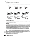
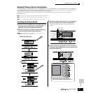
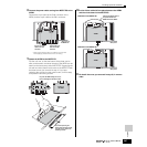
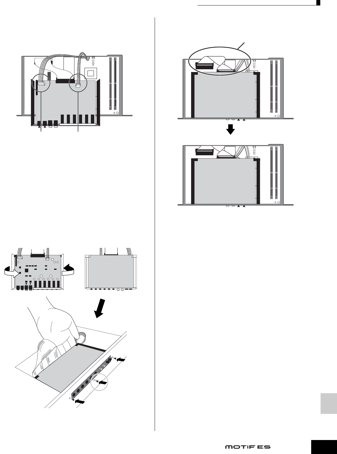
8 Connect the power cable coming from MOTIF ES to the
AIEB2.
Connect the 3-pin cable to the CN3 connector of the
AIEB2, and the 4-pin cable to the CN1 connector.
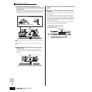
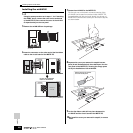
9 Fasten the AIEB2 to the MOTIF ES.
Flip the unit over, so that the bottom of the plate can be
seen, and that each connector section of the AIEB2 can be
seen from the back (rear) side of MOTIF ES. Supporting the
unit with one hand, attach it to the rear of the MOTIF ES with
the three screws you removed in step 4. If you start
replacing the screws from the center screw, it will be easy
to replace the remaining screws.
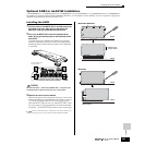
10Let the ribbon cable fall into place between the AIEB2
and the circuit board of the MOTIF ES.
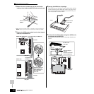
11Re-install the cover you removed in step #3, in reverse
order.
Connect the 4-pin
cable to the CN1
connector
Connect the 3-pin
cable to the CN3
connector
↓ Rear panel of
the MOTIF ES
* Make sure to properly match the cables and connectors.
Avoid applying excessive force when connecting.
Flip over the AIEB2 taking care not to
bend or damage the flat ribbon cable.
If you start replacing the
screws from the center screw,
it will be easy to replace the
remaining screws.
Bottom of
the AIEB2
AIEB2
AIEB2
↓ Rear panel
Slide the flat ribbon cable in
the space between the
MOTIF ES and the AIEB2.
Underside of the MOTIF ES
Underside of the MOTIF ES
↓ Rear panel