


PM5D/PM5D-RH V2 / DSP5D Owner’s Manual Operating section 107
12
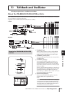
Talkback and Oscillator
Using the oscillator
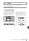
The PM5D contains a test oscillator. By outputting the oscillator signal to the desired bus you can check the operation of con-
nected devices or test the acoustics of a hall.
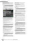
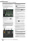
1
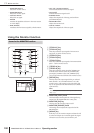
Repeatedly press the [MON/CUE] key of the
DISPLAY ACCESS section until the OSCILLA-
TOR screen appears.
2
Click a button in the OSC MODE section to
select the type of oscillator to output, from the
following choices.
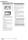
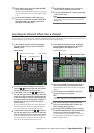
3
Use the knobs and buttons of the PARAME-
TERS area to adjust the oscillator parameters.
The parameters that can be adjusted will depend on the
type of oscillator you selected in step 2. For example if
you selected SINE WAVE 1CH as the oscillator type,
the PARAMETERS area will contain the following
parameters.
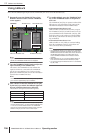
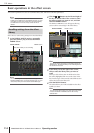
4
Click a button in the BUS ASSIGN area to
select the oscillator signal output destination
from the following choices.
Hint
• If you selected SINE WAVE 2CH as the oscillator type, the
L-channel signal of the oscillator will be sent to odd-num-
bered buses (or the L output jack) and the R-channel signal
of the oscillator will be sent to even-numbered buses (or the
R output jack).
• You can use the OSC OUT area to directly output the oscil-
lator signal from an output jack or slot (
➥
p.237).
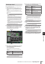
5
Press the OSCILLATOR [ON] key of the OSCIL-
LATOR section.
The oscillator signal will be sent to the bus you selected
in step 4. When you press the key again, the oscillator
will turn off.
Hint
The OSCILLATOR [ON] key of the panel and the OSC ON/
OFF button in the screen are linked.
Note
If the OSCILLATOR [ON] key is off, and a screen other than
the OSCILLATOR screen (TALKBACK function) is displayed,
pressing this key will only display the OSCILLATOR screen;
the key will not turn on. When you press the key once again, it
will turn on.
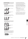
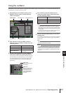
SINE WAVE 1CH button Sine wave x 1 channel
SINE WAVE 2CH button Sine wave x 2 channels
PINK NOISE button Pink noise
BURST NOISE button
Burst noise (repeated output
of pink noise)
OSCILLATOR BUS ASSIGN areaOSC MODE area
PARAMETERS areaOSC OUT area
FREQ knob
Adjusts the frequency of
the sine wave output from
the oscillator. You can
choose preset frequen-
cies by clicking the but-
tons below.
LEVEL knob
Adjusts the output level of
the oscillator.
MIX 1–24 MIX buses 1–24
MATRIX 1–8 MATRIX buses 1–8
STEREO AL/R STEREO A bus L/R channels
STEREO BL/R STEREO B bus L/R channels