


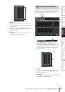

PM5D/PM5D-RH V2 / DSP5D Owner’s Manual Reference section 229
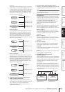
Information shown
in the display
Function
menu
Global
functions
Output
functions
Input
functions
Appendices
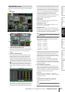
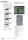
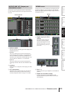
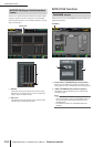
In this screen you can specify the amount of attenuation
for each output channel and for each output channel of an
I/O card.
A DISPLAY MODE
Select the channels that will appear in the display, from
the following choices.
• OUTPUT
The screen will show the amount of attenuation for
output channels (MIX channels 1–24, MATRIX chan-
nels 1–8, STEREO A L/R channels, STEREO B L/R
channels), CUE L/R channels, MONITOR L/R/C chan-
nels, and 2TR OUT DIGITAL 1–3 L/R channels.
• SLOT 1-4
The screen will show the amount of attenuation for
each output channel of the I/O cards installed in slots
1–4.
B ø (phase)
If this button is on, the phase of the output port will be
reversed.
C ATT (Attenuation)
Adjusts the amount of attenuation for each channel.
Move the cursor to the box, and turn the [DATA]
encoder to adjust the value in a range of –9 to 0 dB.
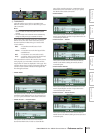
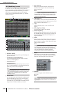
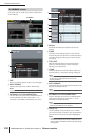
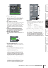
In this screen you can turn dithering on/off and specify the
bit depth for dithering. These settings are made individu-
ally for each digital output jack and each output channel of
the digital I/O cards.
A Digital output jack dither
settings
Specify the number of bits (16,
20, 24 bits) used when dither-
ing the output signals from 2TR
DIGITAL OUT jacks 1–3. If you
select OFF, dithering will not be
performed.
B Slots 1–4
This area shows the type of digital I/O card installed in
each slot.
C Digital I/O card dither settings
For each output channel of the digital I/O cards
installed in the slots, specify the number of bits used
when dithering.
OUTPUT PORT ATT (Output port
attenuation) screen
OUTPUT PORT ATT
1 2 3
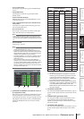
DITHER screen
DITHER
1
2 3