


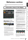
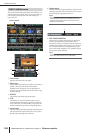

Main area of the display
164 PM5D/PM5D-RH V2 / DSP5D Owner’s Manual Reference section
• PRESENT TIME
Indicates the present time. The time can be specified in
the UTILITY function PREFERENCE 1 screen.
• TIME CODE
Indicates the internal time code being generated by the
PM5D (machine #1), or the time code being received
from an external device. This is the same as the time
code shown in the SCENE function EVENT LIST
screen.
• CASCADE/Fs
Indicates the master/slave status when using a cascade
connection, and the sampling frequency at which the
PM5D system is currently operating.
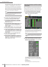
E METER SECTION
Indicates the type of channels that are currently shown
by the meters in the upper left and right of the panel.
You can also click the / buttons to switch this
directly.
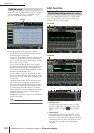
F EVENT indicator
The EVENT indicator is displayed here if the ENABLE
[ALL MANUAL] or ENABLE button is turned on in
the SCENE function EVENT LIST screen.
G FADING/TRACKING indicator
This area shows the FADING indicator while fade time
is being executed, or the TRACKING indicator if
Tracking Recall is available. If both are enabled, FAD-
ING takes priority.
H LCR/LCR [B] indicator
If there is at least one channel for which LCR is turned
on, the LCR indicator is displayed here.
If in the SYS/W.CLOCK function MIXER SETUP
screen the BUS SETUP setting STEREO B is set to USE
AS CENTER BUS, the LCR [B] indicator is displayed
here.
I TB/OSC/DIMM indicator
If talkback, oscillator, or dimmer are on, the respective
TB/OSC/DIMM indicator is displayed here. If more
than one of these are enabled, the display priority is
TB>OSC>DIMM.
J SOLO/INPUT CUE/DCA CUE/OUTPUT CUE/
KEY IN CUE/EFFECT CUE/EXTERNAL CUE
indicator
If Solo or Cue Monitor is enabled, the corresponding
indicator is shown here. If more than one Cue is
selected, only the indicator for the currently-valid Cue
is shown.
K BUSY/RS422/HA/GPI/MIDI indicator
The BUSY indicator is shown here while internal mem-
ory or a PC card in the card slot is being accessed.
When RS422/HA/GPI/MIDI signals are received (in
the case of RS422, when Status is received to indicate a
status change on a connected device), the appropriate
indicator will appear briefly. If more than one of these
conditions occur simultaneously, the display priority is
BUSY>RS422>HA>GPI>MIDI.
Note
In the case of MIDI signals, the indicator will light if signals are
received at the MIDI connector, USB connector, or slots 1–4.
However, active sensing, MIDI clock, and quarter time code
messages will not cause the indicator to light.
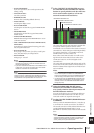
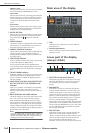
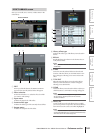
Main area of the display
A Tabs
Click this area to switch between screens within the
selected function.
B Function parameters
This area shows parameters for the currently selected
function or screen.
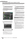
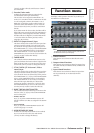
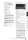
Lower part of the display
(always visible)
A SELECTED CH (Selected channel)
Indicates the type and name of the channel currently
selected by the [SEL] key. You can also move the cur-
sor and turn the [DATA] encoder to change this
directly.
B MACHINE ID
If the DSP5 is cascade-connected, this indicates the
machine (PM5D or DSP5D) #1–#3 that is being con-
trolled from the panel. You can also move the cursor
and turn the [DATA] encoder to change this directly.
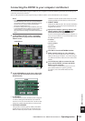
When you switch machines, the screen background
color and the constantly displayed screen (except for
time code) will also change to the settings of the
machine that is now being controlled. The screen back-
ground color can be specified for each machine in the
UTILITY function PREFERENCE 2 screen. The indica-
tor above will light only for the machine ID number
that is cascade-connected.
C MIX SECTION
Indicates the encoder mode currently selected in the
MIX section. In MIX SEND mode this indicates
“SEND,” in MIX MASTER mode this indicates “MAS-
TER,” and if a shortcut operation has been used to
select TO MATRIX mode this indicates “TO
MATRIX.” You can also move the cursor and turn the
1
2
5 6 7 9
1 32 4
8