


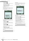
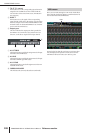
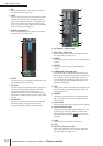
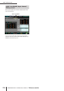

INPUT VIEW function
312 PM5D/PM5D-RH V2 / DSP5D Owner’s Manual Reference section
D EQ
Refer to the explanation of the OUTPUT VIEW func-
tion CH VIEW screen (➥ p.270).
E GATE
This area shows the amount of gain reduction and the
output level of the gate, a mini-graph showing the
approximate response of the gate, and the gate on/off
status. You can also switch the gate on/off from this
screen. If you click the mini-graph, the GATE PARAM
screen for that channel will appear.
F COMP (Compressor)
Refer to the explanation of the OUTPUT VIEW func-
tion CH VIEW screen (➥ p.270).
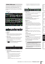
G DELAY
In this area you can view and edit the delay time of the
internal delay and its on/off status.
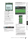
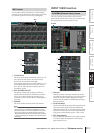
H TO MIX
In this area you can specify the send level, output posi-
tion, and on/off status of the signals sent from the
corresponding input channel to MIX buses 1–24.
(Operation is the same as in the TO MATRIX area of
the OUTPUT VIEW function CH VIEW screen.) Refer
to p.270.
I TO STEREO
Here you can specify the on/off status, pan, and FOL-
LOW PAN settings of the signal sent from the
corresponding input channel to the STEREO bus.
J DCA group / Mute group
K Recall safe / Mute safe
Refer to the explanation of the OUTPUT VIEW func-
tion CH VIEW screen (➥ p.271).
L DIRECT
Turns direct output on/off for the corresponding input
channel.
M INSERT
Turns insert on/off for the corresponding input
channel.
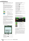
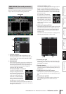
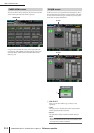
N SURROUND (Surround pan)
If surround mode is enabled, the surround pan posi-
tion of the corresponding input channel is indicated by
the O symbol in the surround pan grid and also as a
front/rear/left/right coordinate position. If you click
the surround pan grid, the SURR PARAM screen for
that channel will appear.
O LCR
Here you can switch LCR mode on/off, and adjust CSR
(the level of the CENTER channel relative to the L/R
channels) (➥ p.267).
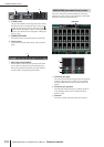
P LIBRARY
This button accesses the INPUT CH LIBRARY screen
(➥ p.316), where you can store/recall input channel
library settings.
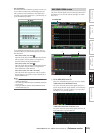
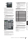
Q Level meter
This level meter indicates the input level of the channel.
R Signal detection point
This is the point at which the signal level shown in the
level meter (
Q) is detected (PRE ATT, PRE GATE,
PRE FADER, POST FADER, or POST ON). You can
edit this setting by clicking the / buttons at the left
and right.
S Fader
This controls the input level of the channel.
T CUE
U ON/OFF (Channel on/off)
Refer to the explanation of the OUTPUT VIEW func-
tion CH VIEW screen (➥ p.271).
7
9
8
K
J
L
M
N
O
P
Q
R
S
T
U