


MIDI REMOTE function
194 PM5D/PM5D-RH V2 / DSP5D Owner’s Manual Reference section
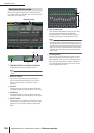
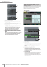
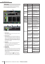
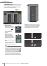
Here you can make settings for GPI (General Purpose
Interface) input/output, used to transfer control signals
between the PM5D and an external device.
A GPI IN port
These are the numbers of the GPI IN ports for which
you can make settings.
B GPI IN status
The yellow bar indicates the input signal voltage state
of the corresponding port. If the bar is not shown, the
signal is in the grounded state; if the bar is displayed to
the right edge, the signal is at the high level state. Use
the POLARITY (
3) field to select whether the signal is
active when low or high.
C POLARITY
This selects how GPI IN on/off will be detected. You
can choose Low Active (active when the key is
grounded) or High Active (active when key is open, or
when a high level signal is input).
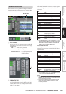
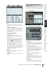
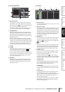
D FUNCTION
E PARAMETER
These fields indicate the function that is executed when
the corresponding GPI IN port becomes active (or the
function that is controlled by the voltage value being
input from the GPI IN port), and option parameters
for that function.
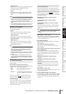
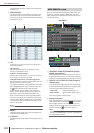
To edit the settings, click the button at the left to
open the GPI IN PORT ASSIGN window, and select
the function and parameter from the following table.
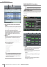
GPI screen
GPI
1 2
3 4 5
FUNCTION PARAMETER PM5D operation
NO ASSIGN — No assignment
MONITOR
DIMMER ON
Switches the Dimmer
function on/off
SOURCE=
[monitor source
name]
Switches the monitor
source
MONO ON
Switches the monitor sec-
tion [MONO] key on
TALKBACK
ON
LATCH
Switches the Talkback
function on/off (latched
operation)
UNLATCH
Switches the Talkback
function on/off (unlatched
operation)
CH ON-
LATCH
[channel name]
Switches the channel on/
off (latched operation)
CH ON-
UNLATCH
[channel name]
Switches the channel on/
off (unlatched operation)
FADER
LEVEL
[channel name]
Modifies the fader value
(LEVEL parameter)
according to the voltage
SUR-
ROUND PAN
FRONT-REAR
PAN [SEL]
according to the voltage.
LEFT-RIGHT
PAN [SEL]
Modifies the surround pan-
ning (left/right) of the
selected channel accord-
ing to the voltage.
FRONT-REAR
PAN [ODD]
Modifies the surround pan-
ning (front/rear) of the
selected odd-numbered
channel according to the
voltage.
LEFT-RIGHT
PAN [ODD]
Modifies the surround pan-
ning (left/right) of the
selected odd-numbered
channel according to the
voltage.
FRONT-REAR
PAN [EVEN]
Modifies the surround pan-
ning (front/rear) of the
selected even-numbered
channel according to the
voltage.
LEFT-RIGHT
PAN [EVEN]
Modifies the surround pan-
ning (left/right) of the
selected even-numbered
channel according to the
voltage.
USER
DEFINED
KEY FUNC-
TION
[User Defined
key bank / key
number]
While the external input is
active, executes the same
operation as when the
selected User Defined key
is pressed
USER
DEFINED
KEY LED
[User Defined
key bank / key
number]
While the external input is
active, lights the LED of
the selected User Defined
key
PEAK HOLD
ON
—
Switches the Peak Hold
function on/off
OSCILLA-
TOR ON
Switches the Oscillator on/
off
SOLO ON
Switches the Solo func-
tion on/off