


7 Using the Selected Channel section
70 PM5D/PM5D-RH V2 / DSP5D Owner’s Manual Operating section
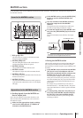
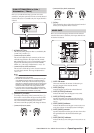
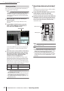
E EQ [Q] encoder
Adjusts the Q (steepness) of each band. This encoder
does nothing for bands whose EQ type is set to shelv-
ing, LPF, or HPF.
F EQ [FREQUENCY] encoder
Adjusts the center frequency (or cutoff frequency) at
which each band will be boosted or cut.
G EQ [FREQUENCY] indicator
Indicates the center frequency (or cutoff frequency) at
which boost/cut will occur, in units of kHz or Hz. (The
indicator for the displayed unit will light.)
H EQ [GAIN] encoder
Adjusts the amount of cut/boost for each band.
I [] key
If this key is on, the corresponding LOW band EQ will
be switched to shelving type. In this case, the LOW
band EQ [Q] knob will have no function.
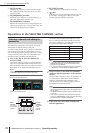
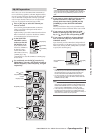
Operations in the SELECTED CHANNEL section
The SELECTED CHANNEL section always controls the
channel that was last selected by its [SEL] key.
To select an input channel, press a [SEL] key in the INPUT
channel strip or ST IN/FX RTN channel strip. (If neces-
sary, switch the layer before pressing a [SEL] key.) To select
an output channel, press a [SEL] key in the MIX section,
MATRIX section, or STEREO A/B channel strip.
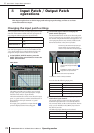
1
Press a [SEL] key to select the channel you
want to control.
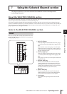
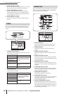
The number and name of the currently selected chan-
nel is shown in the SELECTED CH area at the lower
left of the display, and by the name indicator and num-
ber indicator in the SELECTED CHANNEL section.
Note
If the console is cascade-connected to the DSP5D, the
MACHINE ID field will show the machine ID number.
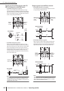
The number shown in the number indicator is as fol-
lows. If a channel is paired, the decimal point for the
lowest place will light. For a FX RTN channel, the deci-
mal point for the highest place will light.
Hint
• In the case of stereo channels (ST IN/FX RTN channels,
STEREO A/B channels), you can switch between L/R by
pressing the same [SEL] key.
• You can also switch the channel by using the CH [DEC] key
/ CH [INC] key of the SELECTED CHANNEL section.
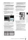
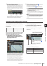
2
Use the controls of the SELECTED CHANNEL
section to edit the parameters of the selected
channel.
When you select a channel in step 1, the parameter val-
ues of that channel will be shown by the LEDs and
indicators of the SELECTED CHANNEL section.
These parameters can be edited using the controls of
the SELECTED CHANNEL section.
Hint
• Gate, compressor, and EQ/HPF operations are explained in
the second half of this chapter; refer to the appropriate sec-
tion for details.
• For details on DCA group and mute group operations, refer
to p.82, 83.
• If you operate a parameter that is selected for AUTO DIS-
PLAY in the PREFERENCE 1 screen, the screen associated
with that parameter will appear automatically.
3
In the same way, select other channels and
edit their parameters.
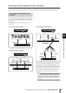
Selecting a channel and editing its
parameters
CH 1
Number of the selected channel
Name of the selected channel
Name
indicator
The name of
the selected
channel
Number
indicator
The number
of the
selected
channel
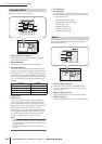
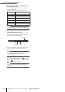
Selected channel Number indicator
Input channels 1–48 1–48
ST IN/FX RTN channels 1–4 (L/R) 1L./1r. – 4L./4r.
MIX channels 1–24 1–24
MATRIX channels 1–8 1–8
STEREO A/B channels (L/R) AL., Ar., BL., Br.