


PM5D/PM5D-RH V2 / DSP5D Owner’s Manual Operating section 65
7
Using the Selected Channel section
This chapter explains how you can use the SELECTED CHANNEL section to control input chan-
nels and output channels.
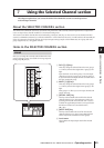
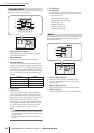
About the SELECTED CHANNEL section
The SELECTED CHANNEL section lets you edit the mix parameters of the currently selected input channel or output chan-
nel; it corresponds to a channel module of a conventional analog mixer.
This section controls the channel that was last selected by pressing its [SEL] key. (In the case of an ST IN channel, FX TRN
channel, or STEREO A/B channel, you will select either the L or the R channel.) However, you will be able to edit essentially all
of the mix parameters (head amp settings, EQ/compressor/gate settings, output to the STEREO bus, DCA group and mute
group assignments, etc.) using panel controls.
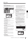
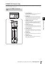
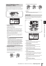
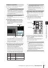
Items in the SELECTED CHANNEL section
Here you can assign the currently selected channel to DCA
groups and mute groups. (For details on DCA groups and
mute groups ➥ p.82, 83)
A DCA [1]–[8] keys
These keys assign the selected channel to DCA groups
1–8. The key LED for the assigned DCA group(s) will
light.
Input channels can use DCA groups 1–8, and output
channels can use DCA groups 7/8. For DCA groups 7/
8, input channels and output channels can both exist in
the same-numbered group.
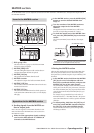
B MUTE [1]–[8] keys
These keys assign the selected channel to mute groups
1–8. The key LED for the assigned mute group(s) will
light.
Mute groups 1–8 allow you to mix input channels and
output channels.
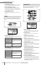
C [RECALL SAFE] key
This key switches Recall Safe on/off for the selected
channel. If this key is on, the parameters of the corre-
sponding channel will not be affected when a scene is
recalled. The applicable parameters can be specified in
the RECALL SAFE screen (SCENE function)
(➥ p.182).
D [MUTE SAFE] key
This key switches Mute Safe on/off for the selected
channel. If this key is on, the corresponding channel
will be temporarily excluded from mute groups.
E Level meter
This indicates the input/output level of the selected
channel.
7
Using the Selected Channel section
GROUP
3
4
5
1 2