


8 Input Patch / Output Patch operations
80 PM5D/PM5D-RH V2 / DSP5D Owner’s Manual Operating section
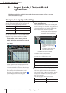
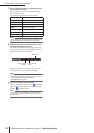
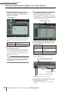
Directly outputting the signal of an input channel
Here’s how the signal being input to an input channel or ST IN channel can be output directly from the desired output jack.
1
In the DISPLAY ACCESS section, press the
INPUT [PATCH] key several times to access the
DIRECT OUT PATCH screen (INPUT PATCH
function) shown below.
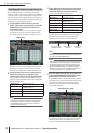
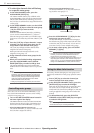
In this screen you can select the output port that will
directly output the input signal of an input channel or
ST IN channel. You can select the following output
ports.
2
Click the grid at which the desired channel
and output port intersect.
The procedure is the same as in the INPUT PATCH
screen or OUTPUT PATCH screen. The SELECTED
PATCH area at the upper left of the screen shows the
channel and output port corresponding to the grid at
which the cursor is located.
Note
With the procedure up to this point, the selected channel and
output port are now patched. However, please note that direct
output is not actually enabled until you turn on the DIRECT
OUT ON/OFF button in the INSERT/DIRECT OUT screen
described below.
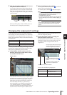
3
Press the INPUT [PATCH] key several times to
access the INSERT/DIRECT OUT POINT screen
(INPUT PATCH function) shown below.
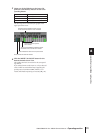
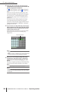
In the INSERT/DIRECT OUT POINT screen (INPUT
PATCH function) you can switch direct output on/off,
and select the direct out point (the location from which
the signal is taken for direct output).
4
Choose the direct out point for each channel
from the following choices, and turn on the
appropriate button.
The selected point is indicated by the graphic in the
upper part of the screen.
5
Click the DIRECT OUT ON/OFF button for the
desired channel to turn it on.
This enables direct output for the corresponding
channel.
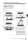
SLOT OUT 1–4
Output channels of an I/O card
installed in slots 1–4
2TR OUT D1–D3 2TR OUT DIGITAL jacks 1–3 (L/R)
DIRECT OUT PATCH
PRE ATT Immediately before the attenuator
PRE HPF Immediately before the HPF
PRE EQ
Immediately before the EQ (immedi-
ately after the PRE EQ of the
INSERT I/O)
PRE FADER Immediately before the fader
POST ON Immediately after the [ON] key
INSERT/DIRECT OUT POINT
Select the direct out point
for each channel.
The “D” symbol indicates the direct out point
for the channel at which the cursor is located
Switch direct out on/off
for each channel.
These indicate the number of the input channels.
These indicate the name of the input channels.