


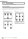

18 Surround pan
144 PM5D/PM5D-RH V2 / DSP5D Owner’s Manual Operating section
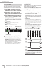
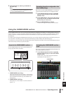
❏ If the MIX section [MIX MASTER] key is on
A Output level
The encoders adjust the output level of each surround
channel.
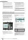
Basic settings for surround buses
Here’s how to choose either 3-1ch, 5.1ch, or 6.1ch as the surround mode, and make settings for the MIX buses you will use as
surround buses.
1
According to the surround mode you intend to
use, connect an appropriate playback system
to MIX OUT jacks 1–8 or MIX OUT jacks 9–16.
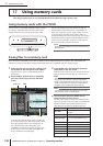
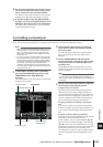
2
In the DISPLAY ACCESS section, repeatedly
press the [MATRIX/ST] key to access the SURR
SETUP screen.
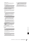
In order to use a surround mode, you will first choose
a surround mode, and then specify the MIX buses that
will be the surround output destinations.
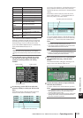
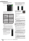
3
Click a button in the SURROUND MODE area
to select the desired surround mode.
When you click a button a window will appear, asking
you to confirm that you want to switch the surround
mode.
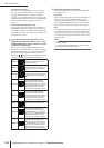
Click the OK button to enable the surround mode you
selected. For example if you switch to 6.1ch mode, the
screen display will change as follows.
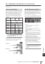
4
In the SURROUND BUS ALLOCATION area,
press the MIX 1-8 button or the MIX 9-16 but-
ton to select the MIX buses you want to use as
surround buses.
You can select either MIX buses 1–8 or MIX buses 9–
16. When you click a button a window will appear, ask-
ing you to confirm that you want to change the MIX
bus allocation.
When you click the OK button, the selected MIX buses
will be allocated as surround buses, and will be
assigned to surround channels according to the cur-
rent surround mode.
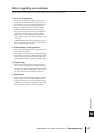
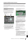
5
If you want to change the surround channel
assignments, click the / buttons at the left
and right of each field in the bus assign area,
and press the [ENTER] key (or click within the
box) to confirm the setting.
When the setting is confirmed, the previously-selected
bus and the newly-assigned bus will be exchanged.
Hint
You can initialize the surround channel assignments by click-
ing the INIT button located at the right of the bus assign area.
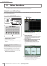
1
SURR SETUP
SURROUND MODE area
SURROUND BUS
ALLOCATION area
Bus assign area
SURR SETUP