


5 Input channel operations
46 PM5D/PM5D-RH V2 / DSP5D Owner’s Manual Operating section
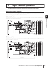
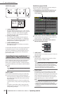
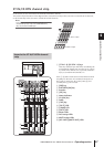
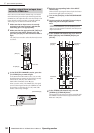
I [CUE] key
This key lets you cue-monitor the signal of the input
channel.
J [TO ST] LED
This LED will light when the signal sent from the input
channel to the STEREO bus is on.
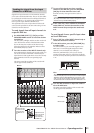
K [COMP] LED
This indicates the operational status of the compressor
for the input channel. This will be dark when the gain
reduction amount is 0 dB, dimly lit when it is 0–10 dB,
and lit when it is greater than 10 dB.
L [GATE] LED
This indicates the operational status of the gate for the
input channel. This will be dark when the gain reduc-
tion amount is 0 dB, dimly lit when it is 0–30 dB (or 0–
10 dB when ducking), and lit when greater than this.
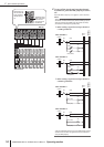
M Meter LEDs
This is a six-point LED meter that indicates the input
level of the input channel. OVER indicates clipping
level, and –6 to –60 indicate the level of the signal rela-
tive to clipping level (0 dB). The level detection point
can be switched.
N DCA assign LEDs
The LED of the DCA group to which that input chan-
nel is assigned will light.
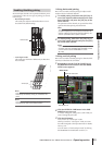
O MUTE assign LEDs
The LED of the mute group to which that input chan-
nel is assigned will light.
P [RCL SAFE]/[MUTE SAFE] LEDs
The corresponding LED will light when recall safe or
mute safe is enabled for the input channel.