


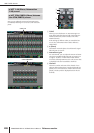
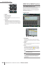

INPUT GATE/COMP function
292 PM5D/PM5D-RH V2 / DSP5D Owner’s Manual Reference section
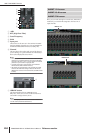
F Level meters
These meters indicate the
amount of gain reduction
(GR), the peak level before
(PRE) and after (POST)
the compressor, and the
peak level of the key-in
signal (KEY IN) that
causes the compressor to
operate. If the signal clips,
the OVER segment will
light.
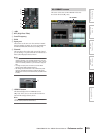
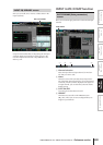
G Type
Indicates the type of the currently selected compressor.
H STEREO LINK
This specifies whether compressor parameter settings
and key-in signal operation will be linked for adjacent
odd-numbered/even-numbered input channels (STE-
REO LINK button on), or will be independent
(STEREO LINK button off). (For details on compres-
sor stereo link ➥ p.254)
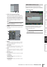
I Compressor graph
This graph displays the approximate response of the
compressor.
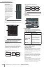
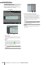
J KEY IN SOURCE
Select the desired key-in signal from the following
choices.
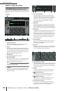
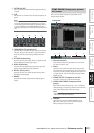
K THRESHOLD (Threshold level)
L RATIO
M ATTACK (Attack time)
N RELEASE (Release time)
O GAIN
P KNEE
These parameters are the same as in the OUTPUT
COMP function COMP PARAM screen (➥ p.255).
6
87
9
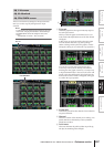
SELF PRE EQ
The pre-EQ signal of the currently
selected input channel
SELF POST EQ
The post-EQ signal of the currently
selected input channel
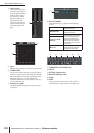
CH 1–48 POST EQ The post-EQ signal of the corre-
sponding input channel (however,
you can only choose channels
belonging to the same group,
within the seven groups CH1–8,
CH9–16, CH17–24, CH25–32,
CH33–40, CH41–48, and ST IN
1L/1R–4L/4R)
ST IN 1L/1R–4L/4R
POST EQ
MIX 21–24
The output signal of the corre-
sponding MIX channel immedi-
ately before the output patch
J
K L M N O P