


PM5D/PM5D-RH V2 / DSP5D Owner’s Manual Reference section 225
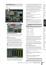
Information shown
in the display
Function
menu
Global
functions
Output
functions
Input
functions
Appendices
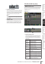
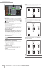
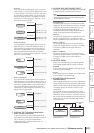
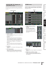
• SLOT 3/4
Up to 30 channels of audio signals can be received via
input channels 1–16 of I/O cards installed in slots 3 and
4. (Since channels 15/16 of SLOT 4 are not used, only
30 channels are actually available.) If you choose this
setting, the signals from the CASCADE IN connector
(channels 1–32) will be assigned to channels 1–16 of
the SLOT IN 3/4 ports instead.
• SLOT 1-4 [CH1-8]
Up to 30 channels of audio signals can be received via
input channels 1–8 of I/O cards installed in slots 1–4.
(Since channels 7/8 of SLOT 4 are not used, only 30
channels are actually available.) If you choose this set-
ting, the signals from the CASCADE IN connector
(channels 1–32) will be assigned to channels 1–8 of the
SLOT IN 1–4 ports instead.
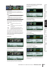
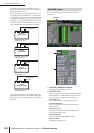
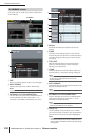
• SLOT 1-4 [CH9-16]
Up to 30 channels of audio signals can be received via
input channels 9–16 of I/O cards installed in slots 1–4.
(Since channels 15/16 of SLOT 4 are not used, only 30
channels are actually available.) If you choose this set-
ting, the signals from the CASCADE IN connector
(channels 1–32) will be assigned to channels 9–16 of
the SLOT IN 1–4 ports instead.
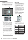
N CASCADE TO (Transmission destination
when cascade-connected)
As the external device to which audio signals will be
transmitted and control signals exchanged over the cas-
cade connection, you can select either PM5D/
PM5D+DCU5D (i.e., a different PM5D unit) or “----”
(transmission disabled).
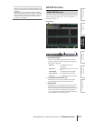
O CASCADE OUT PORT SOURCE SELECT
Select one of the following as the signal source that will
be output from the CASCADE OUT connector.
Hint
If you select a setting other than CASCADE OUT, the same
signals will be output both to the corresponding slots and to
the CASCADE OUT connector.
• CASCADE OUT
The audio signals sent by the cascade function will be
output from the CASCADE OUT connector. If PM5D
is selected as the transmission destination (
N), con-
trol signals for parameter linkage will also be
transmitted and received. The type of signals that are
output can be selected in the CASCADE screen.
• SLOT 3/4
The same audio signals (up to 32 channels) as are out-
put from output channels 1–16 of slots 3/4 will be
output in parallel from the CASCADE OUT connector.
• SLOT 1-4 [CH1-8]
The same audio signals (up to 32 channels) that are
output from output channels 1–8 of slots 1–4 will also
be output in parallel from the CASCADE OUT
connector.
• SLOT 1-4 [CH9-16]
The same audio signals (up to 32 channels) that are
output from output channels 9–16 of slots 1–4 will also
be output in parallel from the CASCADE OUT
connector.
P CASCADE MODE
Choose one of the following two modes of operation
when multiple PM5D units are cascade-connected.
• MASTER
If the Cascade function is enabled, control signals will
be sent to an external PM5D.
• SLAVE
If the Cascade function is enabled, control signals will
be received from an external PM5D.
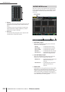
Q BI-DIRECTION (Bi-directional
communication)
When multiple PM5D units are connected, this button
selects whether they will mix each other’s audio signals.
Set the Cascade mode and the BI-DIRECTION button
according to the type of cascade connection, as dis-
cussed below.
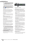
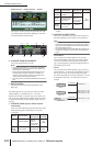
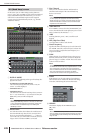
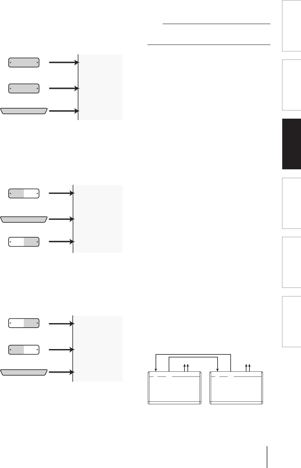
If you cascade-connect two PM5D units in a “ring”
topology (i.e., connect the CASCADE IN connector of
each unit to the OUT connector of the other unit), set
the cascade mode to MASTER on one unit and SLAVE
on the other unit. Turn the BI-DIRECTION button
On for both units.
CASCADE IN
CH 1-16
SLOT 3/4
CH 1-16
SLOT 1/2
CASCADE IN
CH 1-32
SLOT IN 1 (CH 1–16)
SLOT IN 2 (CH 1–16)
SLOT IN 3 (CH 1–16)
SLOT IN 4 (CH 1–16)
30 channels
32 channels
CASCADE IN
CH 1-8
SLOT 1-4
CH 9-16
SLOT 1-4
SLOT IN 1–4 (CH 9–16)
SLOT IN 1–4 (CH 1–8)
CASCADE IN
CH 1-32
30 channels
32 channels
CASCADE IN
CH 9-16
SLOT 1-4
CH 1-8
SLOT 1-4
SLOT IN 1–4 (CH 1–8)
SLOT IN 1–4 (CH 9–16)
CASCADE IN
CH 1-32
30 channels
32 channels
PM5D A
CASCADE
IN
CASCADE
OUT
CASCADE
IN
CASCADE
OUT
PM5D B
CASCADE MODE= MASTER
BI-DIRECTION= ON
CASCADE MODE= SLAVE
BI-DIRECTION= ON
Audio signals of
A+B
Audio signals of
A+B
(Cascade master) (Cascade slave)