


PM5D/PM5D-RH V2 / DSP5D Owner’s Manual Operating section 77
8
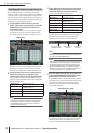
Input Patch / Output Patch operations
Inserting an external device into a channel
You can insert an effect processor or other external device into the signal route of an input channel or output channel. When
doing so, you can specify for each channel the input/output port and insert I/O point that you want to use for insertion.
When inserting an external device into a desired channel,
you can use the rear panel input/output jacks or the input/
output jacks of an I/O card installed in a slot as insert-out/
insert-in jacks.
The following diagrams show typical examples of insert
connections.
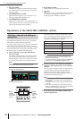
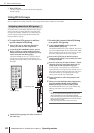
Insert connection example 1
Insert connection example 2
Insert connection example 3
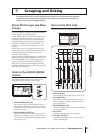
If you are inserting an external digital device via a digital I/
O card as shown in “Insert connection example
3,” you
will need to synchronize the word clock of the PM5D and
the external device. Normally, we recommend that you set
the external device as a word clock slave, and make it fol-
low the PM5D’s word clock. (For details on how to set
your device as a word clock slave, refer to its manual.)
Hint
For the PM5D model, you can also use the rear panel
INSERT IN/OUT jacks to insert an external device into an
input signal, as an alternative to the method described above.
In this case, the insert I/O point is fixed at immediately before
AD conversion. Also, the steps described p.78 will not be
necessary.
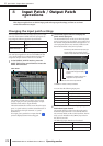
Connecting an external device for
insertion
21
COAXIAL COAXIALAES/EBU AES/EBU AES/EBU AES/EBU
3
21
3
DIGITAL IN
(AES/EBU)
DIGITAL OUT
(AES/EBU)
Effect processor
MY8-DA96MY8-AD96
ANALOG OUT ANALOG IN
Effect processor
AES/EBU
MY8-AE
DIGITAL OUT
(AES/EBU)
INPUT 1/2 OUTPUT 1/2
DIGITAL IN
(AES/EBU)
Effect processor
(female) (male)
Special AES/EBU
cable for MY8-AE