


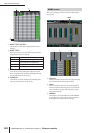

INPUT ø/EQ function
286 PM5D/PM5D-RH V2 / DSP5D Owner’s Manual Reference section
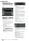
INPUT ø/EQ function
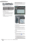
Here you can edit the EQ parameters of the selected input
channel.
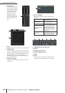
A Channel selection
Selects the input channel (input channel 1–48, STIN
channel 1–4 L/R, FXRTN channel 1–4 L/R).
B Name
This is the name of the currently selected input chan-
nel. If the input channel is paired (or if a ST IN channel
or FX RTN channel is selected), a heart symbol is dis-
played at the right. For an input channel, you can click
this symbol to enable/disable pairing.
C EQ ON/OFF
Turns the EQ on/off for that channel.
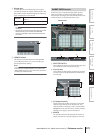
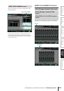
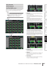
D EQ LINK GROUP
Selects the EQ link group (1–8) to which the EQ of that
channel belongs. EQ parameters are linked for input
channels belonging to the same group.
Note
The input channel EQ link groups are independent from the
output channel EQ link groups.
E LIBRARY
This button accesses the INPUT EQ LIBRARY screen
(➥ p.289), where you can store/recall input channel
EQ library settings.
F ATT (Attenuation)
This knob adjusts the amount of attenuation/gain
immediately following AD conversion in a range of
–96 dB to +24 dB. This is linked with the ATT knob in
the ø/ATT 1-48 screen and ø/ATT STIN/FXRTN
screen. The current value is displayed in the box
located below the knob.
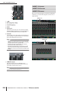
G EQ TYPE
Selects the type of EQ. Turning the TYPE I button on
selects the algorithm used in the 02R series. Turning
the TYPE II button on selects a newly developed algo-
rithm. TYPE II reduces the interference between bands.
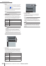
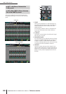
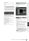
H EQ graph
This graph shows the approximate response of the EQ
parameters. The colored vertical lines indicate the
FREQ (center frequency) of the band for the parame-
ter at which the cursor is located. (The color of each
line matches the knob markings for each band.) The
response curve will change when you edit the Q or
GAIN of each band.
I Level meters
These meters indicate the peak levels before EQ and
after EQ. If the signal clips before or after EQ, the
OVER segment will light.
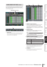
J EQ FLAT
This button resets the GAIN parameters of all bands to
the default value (±0.0 dB). When you click this but-
ton, a confirmation message will appear.
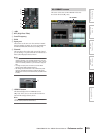
K HPF (High Pass Filter)
The high pass filter located after attenuation and before
EQ can be switched on/off, and you can adjust its cut-
off frequency. The cutoff frequency can be adjusted in
a range of 20–600 Hz.
L Knobs
These knobs adjust the Q, FREQ (center frequency),
and GAIN (amount of boost/cut) for each band.
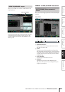
M (LOW shelving)
If this button is on, the LOW EQ will function as a
shelving-type EQ. The Q knob will disappear.
N (HIGH shelving)
If this button is on, the HIGH EQ will function as a
shelving-type EQ. The Q knob will disappear.
O LPF (Low Pass Filter)
If this button is on, the HIGH EQ will function as a
low-pass filter. The Q knob will disappear, and the
GAIN knob is used to switch the LPF on/off.
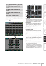
EQ PARAM (EQ parameter) screen
EQ PARAM
1 2 3 54
987 6 J
MK NOL