


PM5D/PM5D-RH V2 / DSP5D Owner’s Manual Reference section 171
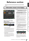
Information shown
in the display
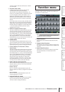
Function
menu
Global
functions
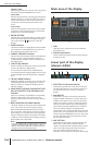
Output
functions
Input
functions
Appendices
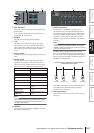
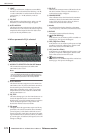
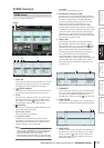
C INSERT (Insert destination)
Selects the location at which the GEQ module will be
inserted. Move the cursor to this box and turn the
[DATA] encoder or click the / buttons at left or
right to display the desired insertion destination, and
then press the [ENTER] key to finalize the change.
You can choose the following insertion destinations.
• INS CH1–INS CH48
Input channel 1–48 insert in/out
• INS STIN1 (L/R)–INS STIN4 (L/R)
ST IN channel 1–4 (L/R) insert in/out
• INS MIX1–INS MIX24
MIX channel 1–24 insert in/out
• INS MTRX1–INS MTRX8
MATRIX channel 1–8 insert in/out
• INS ST A (L/R)
STEREO A channel (L/R) insert in/out
• INS ST B (L/R)
STEREO B channel (L/R) insert in/out
• INS MON (L/R/C) (PM5D only)
MONITOR channel (L/R/C) insert in/out
Note
• When you select the insertion destination here, insert in/out
will be patched simultaneously, and insertion will automati-
cally be turned on for the channel into which the graphic EQ
module was inserted.
• If you move the cursor away without pressing the [ENTER]
key, the setting will revert to its original state.
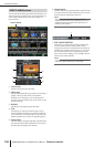
D GEQ/PEQ button
This switches between the 31-band graphic EQ (GEQ)
and 8-band parametric EQ (PEQ).
Note
Even if you switch between GEQ and PEQ, the graphic EQ
and parametric EQ parameters will remember their settings
from before the change.
E EQ ON/OFF button
Switches the currently selected GEQ module on/off.
F LIBRARY
This button accesses the GEQ LIBRARY screen.
G Level meter
This meter indicates the peak level before and after the
GEQ module.
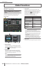
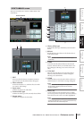
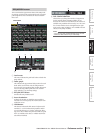
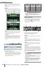
❏ When graphic EQ is selected
H SLOW/FAST
Switches the fall speed of the spectrum analyzer
between slow or fast. This setting does not affect the
meters in other screens or the meters on the panel.
I PEAK HOLD
Switches the peak hold function on/off for the spec-
trum analyzer. The peak level for each band is held
while this button is on. (To reset the peak level display,
turn this button off and then on again). This setting
does not affect the meters in other screens or the
meters on the panel.
J Spectrum analyzer
This is an analyzer that shows a realtime level display
for each band of the input signal.
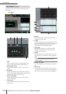
K EQ graph
Indicates the current frequency response of the graphic
EQ.
L Faders
These faders cut/boost the frequency bands of the
graphic EQ. The actual values are shown in the numer-
ical boxes below.
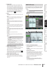
M ASSIGN TO FADERS
These buttons divide the 31 bands of the graphic EQ
into six groups so that you can use the DCA faders to
adjust the boost/cut amount of each band. Click one of
the six buttons A (20.0-100), B (63.0-315), C (200-
1.00k), D (630-3.15k), E (2.00k-10.0k), F (4.00k-
20.0k). DCA faders 1–8 will be assigned to the corre-
sponding region of frequency bands, allowing you to
control them with the DCA faders. At this time, the
divisions of the corresponding faders and the value in
the numerical box screen will turn red in the screen. To
return to the original state, press the DCA (OFF) but-
ton in the screen or the [DCA] button on the panel.
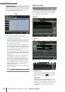
Note
• If the ASSIGN TO FADERS buttons A–F are off, you can
hold down the [SHIFT] button on the panel and press a
FADER MODE section button [A]–[F], and then use the DCA
faders to control the corresponding region of the graphic EQ
in the same way as if you had pressed a button A–F in the
screen.
• The currently selected DCA fader mode (DCA, A–F) is dis-
abled while one of the ASSIGN TO FADERS buttons A–F is
on. At this time, you can also use the FADER MODE sec-
tion buttons [A]–[F] to switch between regions of the graphic
EQ; the button for the selected region will blink, and the
remaining buttons will light.
• If the AUTO ASSIGN button is off, the setting in the ASSIGN
TO FADERS field is cleared automatically when you switch
screens, and the currently selected DCA fader mode will
once again be enabled.
8 9
J
K
L
M
NOP