


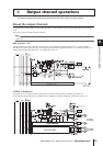


6 Output channel operations
56 PM5D/PM5D-RH V2 / DSP5D Owner’s Manual Operating section
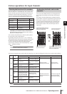
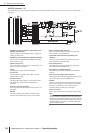
MATRIX channels 1–8
The signals sent from MIX channels or STEREO A/B channels to MATRIX buses are sent via these channels to the MATRIX
OUT jacks.
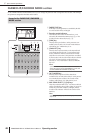
•8 BAND EQ (8 band equalizer) (MIX channels and
STEREO A/B channels)
This is an eight-band (four upper bands + four lower
bands) parametric EQ.
•4 BAND EQ (4 band equalizer) (MATRIX channels)
This is a four-band (HIGH, HIGH MID, LOW MID,
LOW) parametric EQ.
• COMP (Compressor)
This is a dynamics processor that can be used as a com-
pressor, expander, or limiter.
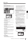
• LEVEL
This adjusts the output level of the channel.
• ON (On/off)
This switches the channel on/off. If this is off, that
channel will be muted.
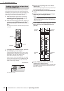
• OUTPUT DELAY
This delays the output signal. It can be used to make
fine adjustments in the relative timing between
channels.
• OUT ATT. (Output attenuator)
This attenuates or boosts the level of the channel’s out-
put signal.
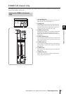
• METER
This meter indicates the output level of the output
channel. The level detection point can be switched.
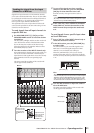
• MIX to STEREO (MIX channels)
This is an on/off switch for the signal sent from the
MIX channel to the STEREO bus.
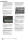
• to MATRIX (MIX channels and STEREO A/B
channels)
This is an on/off switch for the signal sent from the
MIX channel to the MATRIX bus.
• PAN (MIX channels)
This adjusts the panning of the signal sent from the
MIX channel to the STEREO bus.
• BAL (Balance) (STEREO channels)
This adjusts the L/R volume balance of the STEREO
channel.
• LCR (Left/Center/Right) (MIX channels)
This sends the three-channel signal (left/right channels
and a center channel) to the STEREO bus.
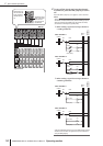
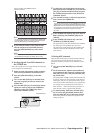
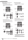
• INSERT
Here you can patch the desired output port and input
port to insert-out/insert-in, allowing an external effect
processor or other device to be inserted. You can
switch the insert-out and insert-in locations.
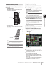
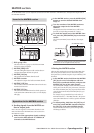
• OUTPUT PATCH
Here, output channels can be assigned to output jacks.
Hint
STEREO A/B channels, and MATRIX channels 1–8 are
always connected to STEREO OUT jacks A/B, and MATRIX
OUT jacks 1–8 respectively. However, you can also make out-
put patch settings to send the signals of these output channels
and MIX channels 1–24 to slots 1–4, the 2TR OUT DIGITAL
jacks or the MIX OUT jacks.