


8 Input Patch / Output Patch operations
74 PM5D/PM5D-RH V2 / DSP5D Owner’s Manual Operating section
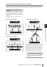
This chapter explains how to edit the input patch and output patch settings, and how to use insert
connections and direct output.
Changing the input patch settings
The input patch section lets you assign input ports to input
channels. In the PM5D’s default state, the input patch set-
tings assign the following signals to input channels.
However, you will need to edit the input patch settings if
you want input signals from an I/O card installed in slots
1–4 or input signals from a 2TR IN DIGITAL jack to be
assigned to an input channel. Here’s how to do this.
1
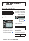
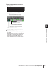
In the DISPLAY ACCESS section, press the
INPUT [PATCH] key several times to access the
INPUT PATCH screen.
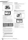
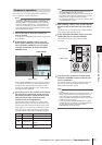
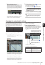
The INPUT PATCH screen is where you can patch
(assign) input ports (rear panel input jacks or input
channels of I/O cards) to input channels.
The horizontal direction of the screen shows the input
ports (i.e., patch sources), and the vertical direction of
the screen shows the input channels (i.e., patch
destinations).
If an input port is patched to an input channel, a
symbol is displayed at the intersecting grid.
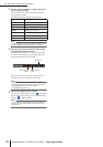
2
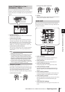
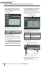
Use the left/right scroll bar to display the
patch-source input port.
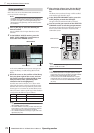
The horizontal direction of the screen shows the patch
source’s input port type, ID number, port number, and
the number of input channels that are assigned to it. To
view input ports that are not currently visible, use the
horizontal scroll bar or the [DATA] encoder.
You can select the following input ports.
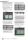
3
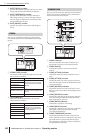
Use the vertical scroll bar to display the patch-
destination input channel.
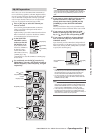
The vertical direction of the screen shows the patch-
destination input channels. To see channels that are
not currently visible, use the vertical scroll bar. Alterna-
tively, you can hold down the [SHIFT] key and turn
the [DATA] encoder.
The following input channels can be selected.
8 Input Patch / Output Patch
operations
Input channels 1–48 Input signals from INPUT jacks 1–48
ST IN channels 1–4
Input signals from ST IN jacks 1–4
(L/R)
FX RTN channels 1–4
Output signals of internal effects 1–4
(L/R)
INPUT PATCH
AD IN 1–48 INPUT jacks 1–48
AD ST IN 1–4 ST IN jacks 1–4 (L/R)
SLOT IN 1–4 Input channels (1–16) of slots 1–4
FX OUT 1–8 Outputs (L/R) of internal effects 1–8
2TR IN D1–D3 2TR IN DIGITAL jacks 1–3 (L/R)
2TR IN A1/A2 2TR IN ANALOG jacks 1/2
CH 1–48 Input channels 1–48
STIN1L/1R–STIN4L/4R ST IN channels 1–4 (L/R)
FXRTN1L/1R–FXRTN4L/4R FX RTN channels 1–4 (L/R)
Indicates the number of the input channel.
Indicates the name of the input channel.
Indicates the number of input ports
assigned to the input channel.
To patch an input port to an input
channel, click this grid to display a “ ”
symbol.
From the top, this shows the input port type
and ID number, the port number, and the
number of input channels currently assigned.