


PM5D/PM5D-RH V2 / DSP5D Owner’s Manual Reference section 277
Information shown
in the display
Function
menu
Global
functions
Output
functions
Input
functions
Appendices
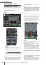
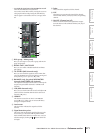
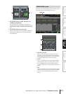
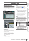
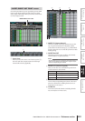
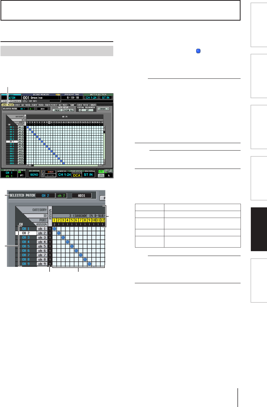
INPUT PATCH function
Here you can assign input ports (INPUT jacks, ST IN
jacks, 2TR IN DIGITAL/ANALOG jacks, input channels of
slots, outputs of internal effects) to input channels.
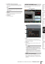
A SELECTED PATCH
This indicates the name and number of the input chan-
nel at which the cursor is located, and the input port.
B CH (Input channel)
This is the number and name of the input channel
(input channel, ST IN channel, FX RTN channel)
assigned to the input port. The channel number at
which the cursor is located will be highlighted. If you
click the name, a window will open allowing you to
assign a name to the channel.
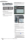
C ASSIGN
For each channel, this indicates the number (1 or 0) of
input ports currently assigned.
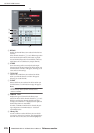
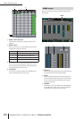
D Grid
This grid lets you patch input ports (horizontal rows)
to input channels (vertical columns). Currently-
patched grids are indicated by a symbol. By clicking
a grid location you can set/cancel patching.
The red lines at the left and top indicate the grid loca-
tion to which you move the cursor.
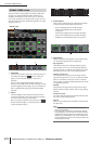
Hint
• If PATCH CONFIRMATION is turned on in the PREFER-
ENCE 1 screen (UTILITY function), a confirmation message
will appear each time you attempt to change a patch set-
ting. If STEAL PATCH CONFIRMATION is turned on, a
confirmation message will also appear when you attempt to
make patch settings that would cause an existing patch to
be modified.
• To move the cursor location rapidly in or out of the grid, hold
down the [SHIFT] key and press the CURSOR [
√
]/[
®
]/[
π
]/
[
†
] keys.
• To move rapidly to left or right inside the grid, turn the
[DATA] encoder. To move up or down, hold down the
[SHIFT] key and turn the [DATA] encoder.
Note
You can patch multiple input channels to a single input port,
but you cannot patch multiple input ports to a single input
channel.
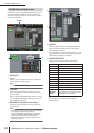
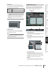
E Input port
From the top, this area indicates the type of input port,
the ID number, the input channel number, and the
number of input channels assigned. The following
types of input port can be selected.
Hint
• The port number is grayed-out for ports that are currently
unavailable.
• If the CASCADE connector is being used as a SLOT IN port,
the port number of the CASCADE connector is displayed in
yellow instead of the SLOT IN port number.
Input functions
INPUT PATCH screen
INPUT PATCH
5
1
2
3 4
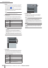
AD IN INPUT jacks 1–48
AD STIN L/R channels of ST IN jacks 1–4
SLOT IN
Input channels of an I/O card installed in
slots 1–4
FX OUT L/R outputs of internal effects 1–8
2TR IN
L/R channels of 2TR IN DIGITAL jacks 1–3
and 2TR IN ANALOG jacks 1/2