


PM5D/PM5D-RH V2 / DSP5D Owner’s Manual Reference section 205
Information shown
in the display
Function
menu
Global
functions
Output
functions
Input
functions
Appendices
D DCA MUTE TARGET
This specifies whether the DCA [MUTE] key will mute
the send to the MIX bus when the send-source to the
MIX bus is PRE FADER. If you specify “POST ONLY,”
the PRE FADER signal will not be muted. If you spec-
ify “PRE & POST,” it will be muted regardless of the
send-source position.
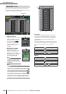
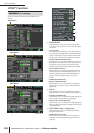
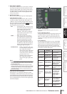
E METER SECTION
Here you can set the following meter-related options.
• FOLLOW INPUT LAYER
This option lets you specify how the [CH 1-24]/[CH
25-48] keys (INPUT channel strip) and [STIN 1-4]/
[FXRTN 1-4] keys will select the layer that is shown by
the meters in the center of the panel and the meters in
the upper right of the panel. Click the / buttons at
left and right to make your choice.
OFF . . . . . . . .Operating the [CH 1-24]/[CH 25-48]
keys will not affect the content shown
by the meters in the center of the
panel. Pressing the [STIN 1-4]/
[FXRTN 1-4] keys will not affect the
content shown by the meters in the
upper right of the panel.
SAME . . . . . . .When you press the [CH 1-24] or
[CH 25-48] key, the corresponding
layer will be shown by the meters in
the center of the panel (if an input
channel is selected in the meter sec-
tion). When you press the [STIN 1-4]
or [FXRTN 1-4] key, the correspond-
ing layer will be shown by the meters
in the upper right of the panel.
ALTERNATIVE . . . When you press the [CH 1-24]
or [CH 25-48] key, the opposite
layer will be shown by the
meters in the center of the panel
(if an input channel is selected
in the meter section). When you
press the [STIN 1-4] or
[FXRTN 1-4] key, the opposite
layer will be shown by the
meters in the upper right of the
panel.
Note
• If this is set to SAME or ALTERNATIVE, the meters in the
center of the panel and the meters in the upper right can be
switched independently.
• If the selected layer is switched from the panel, the layer
shown by the meters will also change. However if you switch
the METER SECTION field in the constantly-displayed area
in the upper part of the screen, the layer selected on the
panel will not change.
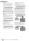
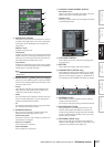
• FOLLOW MIX MASTER MODE
If this button is on, pressing the MIX section [MIX
MASTER] key will cause the meters in the center of the
panel and the meters in the upper right of the panel to
show the MIX/MATRIX channel levels. Press the MIX
section [MIX SEND] key to return to the original input
channel level display.
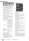
F PANEL OPERATION
Here you can set the following options for panel
operation.
• AUTO CHANNEL SELECT
This specifies whether the corresponding channel will
be selected when you operate a channel’s [ON] key,
fader, or encoder. INPUT CH (input channels) and
OUTPUT CH (output channels) can be turned on/off
separately.
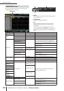
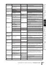
• AUTO DISPLAY
For each of the following items, you can individually
specify whether the related screen will automatically
appear when you use the SELECTED CHANNEL sec-
tion to operate a specific parameter. The following
table shows the parameters corresponding to each but-
ton and the screen that will appear.
Button name
Corresponding
parameters
Screen that appears
HA
Input channel head
amp gain
INPUT HA/INSERT
function screens
PHASE/ATT
Input channel
phase/attenuator
INPUT EQ function ø/
ATT screen
EQUALIZER
EQ-related param-
eters
INPUT EQ/OUTPUT
EQ function EQ
PARAM screen
DYNAMICS
Gate/compressor-
related parameters
INPUT GATE/COMP
function or OUTPUT
COMP function GATE
PARAM or COMP
PARAM screen
DELAY
Delay-related
parameters
INPUT DELAY/OUT-
PUT DELAY function
screens
DCA/MUTE/
SAFE
DCA group / Mute
group / Recall safe-
related parameters
INPUT DCA/GROUP
function or OUTPUT
DCA/GROUP func-
tion DCA GROUP
ASSIGN, MUTE
GROUP ASSIGN or
RECALL SAFE
screen
TO MIX/STE-
REO
TO MIX/TO STE-
REO-related
parameters
PAN/ROUTING func-
tion CH to MIX screen
or SURR PARAM
screen, or MATRIX/ST
function MATRIX/ST
ROUTING screen
TO MATRIX
Send level to
MATRIX bus
MATRIX/ST function
MATRIX/ST ROUT-
ING screen
6