


PM5D/PM5D-RH V2 / DSP5D Owner’s Manual Operating section 67
7
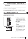
Using the Selected Channel section
Here you can edit the head amp, post AD conversion
attenuator, and phase parameters for the currently selected
channel. This section is available only if an input channel is
selected.
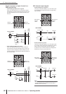
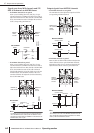
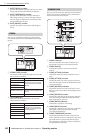
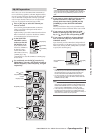
A A[GAIN/ATT] key
This key selects the parameter that is controlled by the
[GAIN/ATT] encoder (
2).
• [GAIN/ATT] key lit (Gain)
The encoder adjusts the input sensitivity of the inter-
nal head amp patched to the input channel (PM5D-
RH and DSP5D only) or of an external head amp that
supports the dedicated protocol (Yamaha AD8HR,
AD824, etc.). The range of adjustment is +10 to –62.
• [GAIN/ATT] key dark (Attenuator)
The encoder controls the post AD conversion attenua-
tor of the input channel. The range of adjustment is
–96 to +24.
Note
• Gain cannot be selected for channels to which an internal/
external head amp is not patched.
• The PAD will be switched on or off internally when the gain
of the PM5D-RH internal head amp is adjusted between –
14 dB and –13 dB. Keep in mind that noise may be gener-
ated if there is a difference between the Hot and Cold output
impedance of the external device connected to the INPUT
connector/ST IN connector when using phantom power.
• If you don’t want it to be possible to select the attenuators,
access the UTILITY function PREFERENCE 1 screen, and
turn ATT OPERATION ON PANEL off (
➥
p.206).
B [GAIN/ATT] encoder
According to the setting of the [GAIN/ATT] key (1),
this encoder controls either the input sensitivity of the
internal/external head amp patched to the input chan-
nel, or the attenuator following AD conversion.
The LEDs around the periphery will change as follows.
• [GAIN/ATT] key lit (Gain)
• [GAIN/ATT] key dark (Attenuator)
C [ø] key
This switches the phase of the selected input channel. If
this key is on, the phase will be reversed.
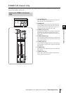
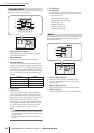
Here you can edit noise gate parameters for the selected
channel. This section is valid only if an input channel or ST
IN channel is selected.
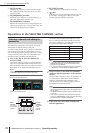
A GATE GR meter
This meter indicates the amount of reduction pro-
duced by the gate of the selected channel.
B GATE [ON] key
Switches the gate on/off for the selected channel.
C GATE [ATTACK] indicator
Indicates the attack time of the gate in msec units.
D GATE [ATTACK] encoder
Specifies the attack time of the gate (the time from
when the signal exceeds the threshold until the gate
opens).
E GATE [HOLD] indicator
Indicates the hold time of the gate in msec units or sec
units (the indicator for the displayed unit will light).
F GATE [HOLD] encoder
Specifies the hold time of the gate (the time from when
the signal falls below the threshold until the gate
closes).
G GATE [DECAY] indicator
Indicates the decay time of the gate in msec units or sec
units.
GAIN/ATTENUATION/ø (Gain /
Attenuation / Phase)
1
2
3
➠
➠
➠
–
(attenuation)
+
(boost)
0
NOISE GATE
9
2
J
8
6
4
3
5
7
1