


PM5D/PM5D-RH V2 / DSP5D Owner’s Manual Operating section 39
4
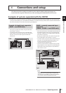
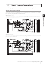
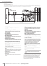
Connections and setup
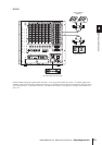
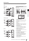
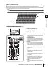
PM5D
DSP5D
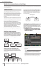
Note
• Sources for which the symbol at the left of the button is
red (UNLOCK) or yellow (UNKNOWN) cannot be selected,
since a valid clock is not being input or the clock cannot be
detected.
• If the PM5D and DSP5D are cascade-connected via the
DCU5D and you’re not synchronizing to an external word
clock being input to the PM5D, you should set the PM5D as
the word clock master and the DSP5D as the slave. This
means that in this case, you’ll select INT for the PM5D, and
CASCADE IN for the DSP5D.
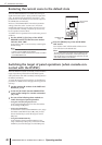
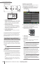
2
In the MASTER CLOCK SELECT area located in
the upper part of the screen, click a button to
select the desired master clock source.
A window will appear, asking you to confirm that you
want to switch the master clock.
3
Click the OK button.
The selected word clock master will be enabled. The
selected word clock master is remembered even if you
turn off the power. As long as the connections have not
been changed, you don’t have to make this setting
again.
Note
• If a digital I/O card (such as the MY8-AE96S) that contains a
built-in SRC (Sampling Rate Converter) is installed in slots,
you can switch the SRC on/off in groups of two channels.
The input signals from channels for which the SRC is turned
on do not need to be synchronized with the PM5D/DSP5D’s
word clock.
• If transferring high sampling rate (88.2 kHz/96 kHz) signals
between the PM5D/DSP5D and an external device, you will
need to select the transmission method. (For details, refer to
p.220)
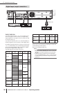
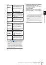
INT 96, INT 88.2,
INT 48, INT 44.1
These settings select the PM5D’s inter-
nal clock. If you select one of these set-
tings, the PM5D will operate as the
word clock master. As necessary,
make settings within your external
devices so that they will operate as
word clock slaves.
W.CLOCK IN
The PM5D will follow the word clock
signal being input from the rear panel
WORD CLOCK IN connector.
CASCADE IN
The PM5D will follow the clock data
being sent from another PM5D con-
nected to the CASCADE IN connector.
2TR IN D1–D3
The PM5D will follow the clock data
included in the input signal from 2TR
IN DIGITAL jacks 1–3.
SLOT 1–4
The PM5D will follow the clock data
included in the input signal from a digi-
tal I/O card installed in slots 1–4. (You
can select a specific pair of adjacent
odd-numbered/even-numbered chan-
nels.)
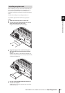
INT 96, INT 88.2,
INT 48, INT 44.1
These settings select the DSP5D’s
internal clock. If you select one of these
settings, the DSP5D will operate as the
word clock master. As necessary,
make settings within your external
devices so that they will operate as
word clock slaves.
W.CLOCK IN
The DSP5D will follow the word clock
signal being input from the front panel
WORD CLOCK IN connector.
CASCADE IN
(D-sub half-pitch
68-pin connector)
The DSP5D will follow the clock data
sent from the other DSP5D, the PM5D,
or the DME64N.
CASCADE IN
(RJ-45 connector)
The DSP5D will follow the clock data
sent from the other DSP5D or the
DCU5D.
SLOT 1–2
The DSP5D will follow the clock data
included in the input signal from a digi-
tal I/O card installed in slots 1–2. (You
can select a specific pair of adjacent
odd-numbered/even-numbered chan-
nels.)