


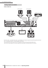
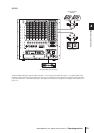

5 Input channel operations
42 PM5D/PM5D-RH V2 / DSP5D Owner’s Manual Operating section
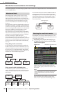
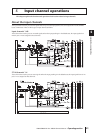
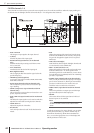
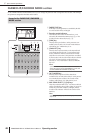
FX RTN channels 1–4
These channels are used mainly to process the return signals (stereo) from the internal effects. When the input patching is in
the default state, the left/right channels of internal effects 1–4 are assigned to these channels.
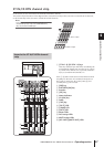
• INPUT PATCH
This assigns an input signal to the input channel.
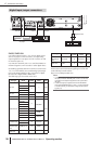
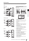
•ø (Phase)
Switches the phase of the input signal.
• MS DECODE (Input channels / ST IN channels
only)
Switches MS decode processing on/off when an MS
mic is connected.
• ATT (Attenuator)
Attenuates/boosts the level of the input signal.
• HPF (High Pass Filter)
This is a high pass filter that cuts the region below the
specified frequency.
•4 BAND EQ (4 band equalizer)
A parametric EQ with four bands; HIGH, HIGH MID,
LOW MID, and LOW.
• GATE (Input channels and ST IN channels only)
This is a dynamics processor that can be used for gat-
ing or ducking.
• COMP (Compressor) (Input channels and ST IN
channels only)
This is a dynamics processor that can be used as a com-
pressor, expander, or limiter.
• INPUT DELAY (Input channels and ST IN channels
only)
This delays the input signal. It can be used to make fine
adjustments in the relative timing between channels.
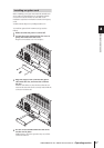
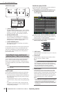
• LEVEL/DCA 1-8
Adjusts the input level of the effect.
• ON (On/off)
Turns the input channel on/off. If off, that channel is
muted.
• PAN
Adjusts the panning of the signal sent from the input
channel to the STEREO bus. If necessary, this pan set-
ting can also be applied to signals sent to two paired
MIX buses.
• LCR (Left/Center/Right)
Sends the three-channel signal (left/right channels and
a center channel) to the STEREO bus.
• MIX 1-24 (Mix send level 1–24)
Adjusts the send level of the signal sent from the input
channel to MIX buses 1–24. As the position from
which the signal is sent to the MIX bus, you can choose
from the following; immediately before the 4-band EQ,
pre-fader, or post-fader.
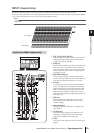
• INSERT (Input channels and ST IN channels only)
Here you can patch the desired output port and input
port to insert-out/insert-in, allowing an external effect
processor or other device to be inserted. You can
switch the insert-out and insert-in locations.
• DIRECT OUT (Input channel and ST IN channels
only)
This can be patched to an output port, and the input
signal sent directly from that output port.
• METER
This meters the level of the input channel. The level
detection point can be switched.
Note
The signal assignments from input patch to input channel can
be edited in the INPUT PATCH function INPUT PATCH
screen.
To edit the parameters of an input channel, you can either
use the panel controllers (e.g., INPUT channel strip, ST
IN/FX RTN channel strip, SELECTED CHANNEL sec-
tion), or access the appropriate screen in the display and
edit the parameters in the screen.