


PM5D/PM5D-RH V2 / DSP5D Owner’s Manual Reference section 235
Information shown
in the display
Function
menu
Global
functions
Output
functions
Input
functions
Appendices
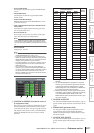
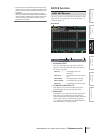
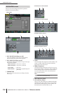
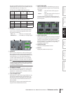
C Talkback input selection
If you want to use an input jack other than the TALK-
BACK jack for purposes of talkback, you can choose it
here from analog inputs AD IN 1–48. The talkback
input selection is not included in the input patch
library.
D HA (PM5D-RH model only)
Here you can switch phantom power on/off and adjust
the gain for the analog input selected in (
3). The
LEVEL volume in the TALKBACK section of the panel
does not affect the talkback input from the analog
input channel. The HA setting is included in the HA
library.
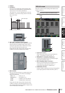
E Level meter (Analog input level meter)
This level meter indicates the peak level of the signal
being input from the analog input selected in (
3).
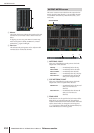
F ON/OFF (Analog input on/off)
This button switches the talkback input selected in (3)
on/off.
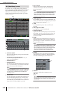
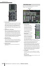
G ON/OFF (Talkback on/off)
This button switches Talkback on/off. This is linked
with the TALKBACK [ON] key in the TALKBACK sec-
tion of the panel.
H NEVER LATCH
This button selects one of the following as the mode in
which the TALKBACK ON/OFF button and the panel
TALKBACK [ON] key will behave.
• If the NEVER LATCH button is off
Talkback will be switched on/off (Latched operation)
each time you click the ON/OFF button or press the
TALKBACK [ON] key. However if you press and hold
down the TALKBACK [ON] key, talkback will stay on
only while you continue holding down the key; talk-
back will turn off when you release the key (Unlatched
operation).
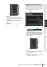
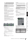
• If the NEVER LATCH button is on
Talkback will be on only while you click and hold
down the ON/OFF button or press and hold down the
TALKBACK [ON] button; talkback will turn off when
you release the button or key (Unlatched operation).
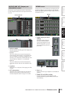
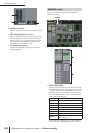
I BUS ASSIGN
Here you can select the bus(es) or output jack(s) from
which the talkback signal will be sent. (Multiple selec-
tions are allowed.)
MIX 1–24 . . . . . . . . MIX bus 1–24
MATRIX 1–8 . . . . . MATRIX bus 1–8
ST A L/R . . . . . . . . . STEREO A bus L/R channels
ST B L/R . . . . . . . . . STEREO B bus L/R channels
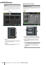
J TALKBACK OUT (Talkback direct output)
This indicates the channel of the output jack / slot that
is selected as the output destination for direct output of
the talkback signal. If more than one output destina-
tion is patched, “...” will be displayed following the
name of the output destination that was found first. If
you want to change the output destination, click the
PATCH button to access the OUTPUT PATCH screen.
6
5
3
4
7
8
9
J