


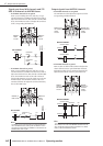

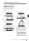

7 Using the Selected Channel section
72 PM5D/PM5D-RH V2 / DSP5D Owner’s Manual Operating section
Here’s how you can use the SELECTED CHANNEL sec-
tion to operate the internal gate.
Note
The PM5D provides two types of built-in gating; GATE and
DUCKING. These operate in different ways. This means that if
you want to use a gate, you must load gate settings of the
desired type from the gate library, and then edit the parame-
ters as desired.
1
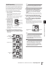
Press a [SEL] key to select the channel you
want to control.
Gate is available only for input channels or ST IN
channels.
2
In the DISPLAY ACCESS section, press the
INPUT [GATE/COMP] key several times to
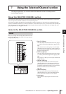
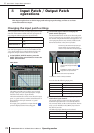
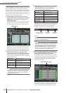
access the GATE LIBRARY screen.
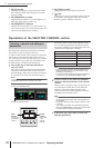
In the GATE LIBRARY screen you can store gate set-
tings in the library, or recall existing data from the
library.
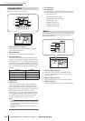
3
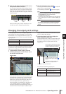
Move the cursor to the scroll bar of the library
list in the lower right of the screen, and turn
the [DATA] encoder to select the library item
that you want to load. (The library item
selected in the list is highlighted.)
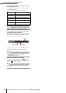
Numbers 001–004 for which an “R” is shown at the
right of the list contain read-only preset library items.
Numbers 001–002 contain preset library items of dif-
ferent types. It is convenient to use these library items
when you want to select a specific type. These numbers
correspond to the different types as follows.
Hint
• The type of the currently selected gate is shown in the
GATE PARAM screen (
➥
p.289).
• The GATE LIBRARY screen also provides other library set-
tings suitable for a wide variety of instruments or purposes.
You can also save your own settings in the library.
• For a detailed explanation of each type of gate, refer to the
Appendices (
➥
p.321).
4
After selecting a library item, click the RECALL
button located at the lower left of the library
list.
The library item you selected in step 3 will be recalled
to the channel you selected in step 1.
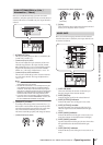
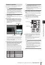
5
In the SELECTED CHANNEL section, press the
GATE [ON] key to make the LED light.
The gate of the selected channel will be activated.
6
You can use the gate controls of the SELECTED
CHANNEL section to edit the gate parameters.
The amount of gain reduction produced by the gate is
shown by the GATE GR meter in the SELECTED
CHANNEL section.
Note
The THRESHOLD LED will not light if the threshold level is
between –55 dB and –72 dB.
Hint
• For details on the function of the gate controls, refer to p.67.
• More detailed parameters for the gate (selection of key-in
signal, stereo link on/off) can be edited in the INPUT GATE/
COMP function GATE PARAM screen (
➥
p.289).
• You can also cause the GATE PARAM screen to appear
automatically when you operate a gate control. This setting
is made in the UTILITY function PREFERENCE 1 screen
(
➥
p.204).
Number Name Type
001 Gate GATE
002 Ducking DUCKING
Gate operations
GATE LIBRARY
Scroll barRECALL button
GATE [ON] key
GATE GR meter