


GEQ function
172 PM5D/PM5D-RH V2 / DSP5D Owner’s Manual Reference section
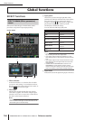
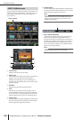
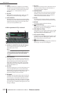
N LIMIT
The range and direction of adjustment controlled by
the faders can be selected from the following: ±15 dB,
±12 dB, ±6 dB (these are valid in both the boost and
cut directions), or –24 dB (valid only in the cut
direction).
O EQ FLAT
Resets all faders to the 0 dB position. When you click
this button, a confirmation message will appear.
P AUTO ASSIGN
This button automates assignments to the DCA faders.
If this button is on, the most recently selected region of
GEQ bands will be assigned to the DCA faders when
you access the GEQ PARAM screen.
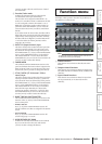
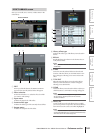
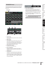
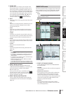
❏ When parametric EQ is selected
Q ASSIGN TO SELECTED CH ON/OFF button
This switches the assignment to the SELECTED
CHANNEL section on/off.
Note
If the AUTO ASSIGN button is off, switching the screen will
make the ASSIGN TO SELECTED CH ON/OFF button turn
off, and you’ll be able to use the SELECTED CHANNEL sec-
tion to operate the parameters of the currently selected
channel.
R AUTO ASSIGN
This button automates assignment to the SELECTED
CHANNEL section. If you leave this button turned on,
the selected frequency band will be assigned to the
SELECTED CHANNEL section when you access the
GEQ PARAM screen if the ASSIGN TO SELECTED
CH ON/OFF button is on.
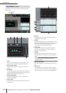
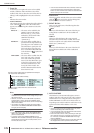
S EQ TYPE
This selects the EQ type. Turn the TYPE I button on to
choose the algorithm used in conventional Yamaha
digital mixers, or turn the TYPE II button on to choose
a newly-developed algorithm. Using TYPE II will
decrease the interference between bands.
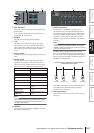
T EQ graph
This graph shows the approximate response of the EQ
parameters. The colored vertical line shows the FREQ
(center frequency) of the band at which the cursor is
located. (The color of each line is the same as the mark-
ings around the knob of each band.) When you edit the
Q or GAIN (gain) of each band, the response curve will
change accordingly.
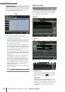
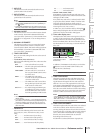
U EQ FLAT
This resets the GAIN parameter of all bands to the ini-
tial value (±0.0 dB). When you click this button, a
confirmation message will appear.
V LOWER/UPPER
These indicators show which four bands (LOWER or
UPPER) are selected in the SELECTED CHANNEL
section of the panel. The text is shown in yellow to
indicate the set of bands that is selected.
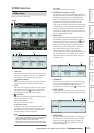
W Knobs
For each band, these knobs adjust the Q, the FREQ
(center frequency), and GAIN (amount of boost/cut).
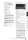
X BYPASS
This button bypasses each band of the EQ.
Y (LOW shelving)
If this button is on, the LOW EQ will be switched to a
shelving-type. The Q knob will disappear.
Z HPF (High Pass Filter)
If this button is on, the LOW EQ will operate as a high
pass filter. The Q knob will disappear, and the GAIN
knob will be used to turn the HPF on/off.
a LPF (Low Pass Filter)
If this button is on, the HIGH EQ will operate as a low
pass filter. The Q knob will disappear, and the GAIN
knob will be used to turn the LPF on/off.
b (HIGH shelving)
If this button is on, the HIGH EQ will be switched to a
shelving-type. The Q knob will disappear.
UT
V
W
Q
R
S
Y
Z
a
b
X