


PM5D/PM5D-RH V2 / DSP5D Owner’s Manual Reference section 321
Information shown
in the display
Function
menu
Global
functions
Output
functions
Input
functions
Appendices
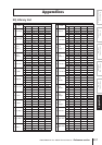
Dynamics Parameters
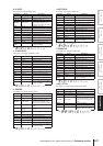
Each channel has a GATE section (input channels and ST IN channels only) and a COMP section. The Gate section includes
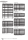
Gate and Ducking types. The Comp section includes Compressor, Expander, Compander Hard (COMP. (H)), and Com-
pander Soft (COMP. (S)) types.
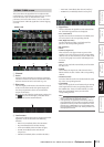
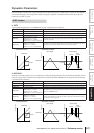
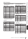
❏ GATE
A gate attenuates signals below a set THRESHOLD level by a specified amount (RANGE).
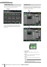
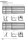
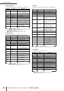
❏ DUCKING
Ducking is commonly used for voice-over applications in which the background music level is reduced automatically when an
announcer speaks. When the KEY IN source signal level exceeds the specified THRESHOLD, the output level is attenuated by
a specified amount (RANGE).
GATE section
Parameter Range Description
THRESHOLD (dB) –72 to 0 (73 points) This determines the level at which the gate effect is applied.
RANGE (dB) –∞, –69 to 0 (71 points) This determines the amount of attenuation when the gate closes.
ATTACK (ms) 0–120 (121 points) This determines how fast the gate opens when the signal exceeds the threshold level.
HOLD (ms)
44.1kHz: 0.02 ms – 2.13 sec
48kHz: 0.02 ms – 1.96 sec
88.2kHz: 0.01 ms – 1.06 sec
96kHz: 0.01 ms – 981 ms (160 points)
This determines how long the gate stays open once the trigger signal has fallen
below the threshold.
DECAY (ms)
44.1kHz: 6 ms – 46.0 sec
48kHz: 5 ms – 42.3 sec
88.2kHz: 3 ms – 23.0 sec
96kHz: 3 ms – 21.1 sec (160 points)
This determines how fast the gate closes once the hold time has expired. The value is
expressed as the duration required for the level to change by 6 dB.
Parameter Range Description
THRESHOLD (dB) –54 to 0 (55 points) This determines the level of trigger signal (KEY IN) required to activate ducking.
RANGE (dB) –70 to 0 (71 points) This determines the amount of attenuation when ducking is activated.
ATTACK (ms) 0–120 (121 points) This determines how soon the signal is ducked once the ducker has been triggered.
HOLD (ms)
44.1kHz: 0.02 ms – 2.13 sec
48kHz: 0.02 ms – 1.96 sec
88.2kHz: 0.01 ms – 1.06 sec
96kHz: 0.01 ms – 981 ms (160 points)
This determines how long ducking remains active once the trigger signal has fallen
below the THRESHOLD level.
DECAY (ms)
44.1kHz: 6 ms – 46.0 sec
48kHz: 5 ms – 42.3 sec
88.2kHz: 3 ms – 23.0 sec
96kHz: 3 ms – 21.1 sec (160 points)
This determines how soon the ducker returns to its normal gain once the trigger sig-
nal level drops below the threshold. The value is expressed as the duration required
for the level to change by 6 dB.
Input Level Time Time
Output Level
Input Level
Output Level
• I/O Characteristics • Time Series Analysis
RANGE
THRESHOLD
THRESHOLD
RANGE
Input Signal Output Signal
ATTACK DECAY
HOLD
Input Level Time Time
Output Level
Input Level
Output Level
• I/O Characteristics • Time Series Analysis
RANGE
THRESHOLD
THRESHOLD
RANGE
Input Signal Output Signal
ATTACK DECAY
HOLD