


PM5D/PM5D-RH V2 / DSP5D Owner’s Manual Reference section 173
Information shown
in the display
Function
menu
Global
functions
Output
functions
Input
functions
Appendices
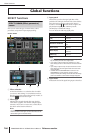
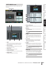
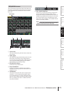
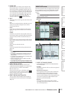
This screen lists the approximate values of the GEQ mod-
ule settings, and shows the input/output levels. The signal
path assignments and on/off status can also be edited in
this screen.
A Level meter
This meter indicates the peak level before and after the
GEQ module.
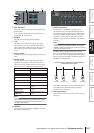
B Fader graph
This indicates the approximate fader position for each
band. When you click this area, the GEQ PARAM
screen for the corresponding GEQ module will appear.
You can also drag and drop this area onto another
GEQ module to copy the GEQ settings.
C GEQ ON/OFF button
Switches the GEQ module on/off.
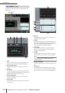
D Insert destination
Indicates the location at which the GEQ module is
inserted. You can also specify the insert location from
within this screen.
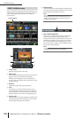
E LINK button
This button indicates the link status of adjacent odd-
numbered → even-numbered GEQ modules. When
you turn this button on, a window will appear, allow-
ing you to select whether the parameters will be copied
from one module to the other, or whether both mod-
ules will be initialized.
F DSP CONFIGURATION
This box lets you change the number of assignments
for the internal effects and GEQ modules. If you
decrease the number of internal effects, the number of
available GEQ modules will increase by one. The num-
ber of internal effects can be changed between eight
units (twelve GEQ modules) to zero available internal
effects (twenty GEQ modules).
Note
If you change the DSP CONFIGURATION setting, the inter-
nal effects or GEQ modules may be muted briefly.
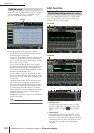
GEQ ASSIGN screen
GEQ ASSIGN
5
1 2 3
4
6