


PM5D/PM5D-RH V2 / DSP5D Owner’s Manual Operating section 15
1
Introduction
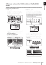
link selection of MIX channels with selection of MIX
SEND SELECT keys. (➥ p.206)
• In the USER DEFINE screen, functions such as DSP5D
CONTROL and ENCODER MODE KEY have been
added to the functions that can be assigned to user-
defined keys. (➥ p.208)
• In the FADER ASSIGN screen, options have been
added, allowing you to use the STEREO/DCA strip sec-
tion to control the monitor/cue level and on/off status.
(➥ p.217)
• In the FADER ASSIGN screen, you can now assign the
desired channels of the DSP5D as well. (➥ p.217)
• In the SECURITY screen, a LOAD LOCK function has
been added, allowing you to disable loading for each
type of file. (➥ p.218)
• In the SECURITY screen, a RECALL LOCK option has
been added, allowing you to lock parameters so that
they will not be changed when a scene or library is
recalled. (➥ p.218)
❏ Input/output functions
• In the OUTPUT PATCH function OUTPUT PATCH
screen, you can now change the patching of output
channels to MIX OUT jacks 1–24. (➥ p.243)
• In the OUTPUT PATCH function INSERT POINT
screen and the INPUT PATCH function INSERT/
DIRECT OUT POINT screen, a SET ALL button and
CLEAR ALL button have been added, allowing you to
turn all channels on/off in a single operation.
(➥ p.246, 281)
• In the OUTPUT PATCH function, a NAME screen has
been added, allowing you to assign names to output
channels for display in various screens (supported from
V1.2). (➥ p.247)
• In the INPUT VIEW function CH JOB screen, channel
settings can now be moved as well as copied. (➥ p.314)
• In the INPUT PATCH function INSERT/DIRECT
OUT POINT screen, PRE ATT has been added as a
direct output transmit location. (➥ p.282)
• In the PAN/ROUTING function MIX SEND VIEW
screen, the send position (PRE/POST) of the signal
sent to the MIX bus is now indicated by the color of the
bar graph. (➥ p.306)
• You can now set a Q of up to 16 for the parametric EQ
in the input channels, output channels, and GEQ
modules.
• You can now set a threshold level of down to –72 dB
for an input channel GATE.
Regarding word clock synchronization
The signal used to synchronize digital audio signal process-
ing is called “word clock.” Normally, one device transmits
a reference word clock signal, and the other devices receive
this word clock signal and synchronize to it.
In order to transmit or receive digital audio signals to or
from an external device via the PM5D/DSP5D’s digital
input/output jacks or via a digital I/O card installed in a
slot, the word clock must be synchronized between the
devices. Be aware that if the word clock is not synchro-
nized, the signals will not be transmitted correctly, and
unpleasant noise will occur.
Hint
• For details on synchronizing the word clock of the PM5D/
DSP5D and external devices, refer to the explanation of
word clock in Operating section “Chapter 4. Connections
and setup” (
➥
p.38), and to the Reference Section “WORD
CLOCK screen” (
➥
p.219).
• As an exception, digital signals that are not synchronized
with the PM5D/DSP5D can be input via a digital I/O card
that contains a sampling rate converter, or via the 2TR IN/
OUT DIGITAL jacks.
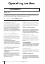
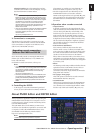
How this manual is organized
This owner’s manual is divided into the following three
sections.
❏ Operating section
This section explains the items on the front and rear pan-
els, connections and setup, and how to operate the PM5D’s
basic functionality. In particular if you have not operated a
digital console before, we recommend that you read chap-
ters 2 through 7 first.
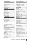
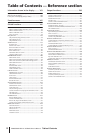
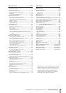
❏ Reference section
This section explains the functionality and operation for all
of the PM5D’s screens. Refer to this section when you want
to learn about the items in the screens.
❏ Appendices
This contains various information such as library lists,
parameter lists for the internal effects, the MIDI data for-
mat, and lists of warning messages and error messages.
In this manual, non-locking panel switches that you press
are called “keys,” and those that change their on/off status
when you push them in (locking types) are called
“switches.” Of the control knobs on the panel, those that
turn from a minimum value to a maximum value are
called “knobs,” while those that turn endlessly are called
“encoders.”
Controls located on the panel are enclosed in square brack-
ets [ ] (e.g., [CUE] key, [PAD] switch) in order to
distinguish them from the buttons and knobs displayed in
the screen. For some controls, the section name is listed
before the [ ] (e.g., CH [ON] key, EQ [FREQUENCY]
encoder).
Unless otherwise specified, references to the PM5D apply
to both the PM5D model and the PM5D-RH model. If
specifications differ between the PM5D model and the
PM5D-RH model, such differences will be noted each time
they occur.
Conventions in this manual