


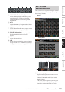
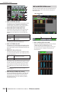

OUTPUT DCA/GROUP function
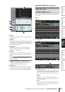
258 PM5D/PM5D-RH V2 / DSP5D Owner’s Manual Reference section
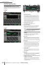
• SAMPLE
The delay time is shown as a number of samples. If you
change the sampling frequency at which the PM5D
operates, the number of samples will change
accordingly.
• msec (milliseconds)
The delay time is shown in units of milliseconds. If this
button is on, the boxes above and below the delay time
knob (
3) will show the same values.
• BEAT
The delay time is shown in units relative to the note
length (considered as 1.0) specified by the tempo
(BPM) and note value (NOTE).
To specify the tempo, you can either use the /
buttons located immediately below the BEAT button,
or repeatedly tap (click) the TAP button, or repeatedly
click a User Defined key that is assigned to [TAP
TEMPO]-[CURRENT PAGE].
• FRAME
The delay time is shown in units of frames.
Use the six buttons located below the FRAME button
to select the number of frames per second.
Hint
• If you change the DELAY SCALE setting of the OUTPUT
DELAY function screen, the DELAY SCALE setting of the
INPUT DELAY function screen will change in tandem.
• The TAP button of the OUTPUT DELAY function is indepen-
dent from the TAP TEMPO button of the internal effect.
• The number of frames per second is linked with the TIME
CODE SETUP field in the EVENT LIST screen (SCENE
function).
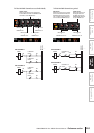
B GANG
This button specifies whether the delay parameters will
be linked for adjacent odd-numbered/even-numbered
channels. This can be specified independently of pair-
ing. If the GANG button is turned on for channels of
differing delay times, turning the delay time knob (
3)
will change the delay times of both channels while
maintaining the difference in their delay time.
C Delay time knob
This knob sets the delay time of each channel. The box
below the knob shows the delay time in the units you
selected in (
1). The box above the knob always shows
the delay time in millisecond units.
D DELAY ON/OFF
This button switches delay on/off. This is linked for
paired channels.
E Channel
This is the number and name of the channel you are
editing. Two paired channels are indicated by a heart
symbol displayed between them. You can click this
symbol to enable/disable pairing.
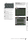
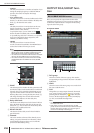
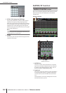
OUTPUT DCA/GROUP func-
tion
Here you can specify the output channels that will be
assigned to DCA groups 7/8. You can use DCA faders 7/8
to uniformly adjust the levels of output channels belong-
ing to the same DCA group.
A DCA group
This is the number of the DCA group. The number
corresponding to the grid where the cursor is located is
highlighted.
B Name
This is the name of the DCA group. You can also click
this area to edit the name.
C Grid
This grid lets you assign output channels (horizontal
rows) to DCA groups (vertical columns). Currently-
patched grids are indicated by a symbol. Move the
cursor to the desired grid and press the [ENTER] key
(or click) to set/disable the assignment.
Hint
• You can also assign an output channel to both DCA groups
for multiple DCA control.
• DCA groups 1–6 are for input channels only, but DCA
groups 7/8 can be used with both input channels and output
channels. DCA groups 7/8 allow you to use both types of
channel in the identically-numbered group.
2
3
4
5
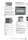
DCA GROUP ASSIGN screen
DCA GROUP ASSIGN
213