


PM5D/PM5D-RH V2 / DSP5D Owner’s Manual Reference section 313
Information shown
in the display
Function
menu
Global
functions
Output
functions
Input
functions
Appendices
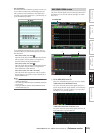
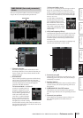
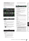
This screen shows the signal flow for two adjacent odd-
numbered/even-numbered input channels or ST IN chan-
nels. In this screen you can also edit some of the
parameters, and access other screens. You can also deter-
mine the location within the signal flow at which clipping
occurred.
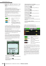
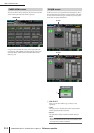
A Channel
B Insert
Except for the fact that this screen depicts input chan-
nels, the contents are the same as the OUTPUT VIEW
function SIGNAL FLOW screen. Refer to p.272.
C Direct out
This area displays information about the direct output
of the two selected channels (the signal output posi-
tion, the port patched to direct out, and the direct
output on/off status).
Here you can also select the signal output position (use
the / buttons at left and right), and switch direct
output on/off (use the ON/OFF button).
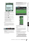
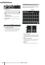
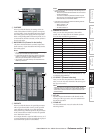
D Level meters
These meters indicate the levels at various points in the
signal flow. Levels are detected at the following
locations.
• PRE ATT (immediately before the attenuator)
• EQ (immediately before and after the EQ)
• GATE (immediately before and after the gate)
• COMP (immediately before and after the
compressor)
• FADER (immediately before and after the fader)
• POST ON (immediately after the CH [ON] key)
• INSERT IN (immediately after the insert point)
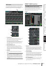
E Signal flow
This area indicates the signal flow of the selected chan-
nel. The following parameters are displayed.
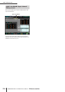
• ATT (Attenuation)
Specifies the amount of attenuation immediately after
AD conversion for the corresponding channel.
• HPF (High Pass Filter)
Specifies the high pass filter on/off and cutoff fre-
quency for the corresponding channel.
• EQ (Equalizer)
• GATE
• COMP (Compressor)
These areas show the approximate response of the
equalizer, gate, and compressor for the corresponding
channel. You can also switch these on/off in this screen,
or click a mini-graph to access the individual parame-
ter screen.
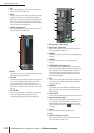
• DELAY
Here you can switch the internal delay on/off and edit
the delay time.
• FADER
This indicates the input level of the channel. This is
linked with the encoder or fader of the corresponding
channel.
• ON/OFF (On/off)
Turns the channel on/off. This is linked with the [ON]
key of the corresponding channel.
• TO STEREO
Here you can specify the on/off status and pan settings
of the signal sent from the corresponding channel to
the STEREO bus. These are linked with the [TO STE-
REO] key and STEREO [PAN] encoder of the
corresponding channel.
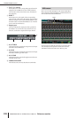
Hint
• If insert or direct out is turned on, the current insert point or
direct out point within the signal flow is shown.
• If the signal clips, the signal flow (horizontal line) after clip-
ping is displayed in red. If an output is turned off so that the
signal does not flow any further, the subsequent flow is dis-
played in gray. If PEAK HOLD is on, the flow indication will
stay red if clipping occurs even once, making it easier to see
that clipping has occurred.
SIGNAL FLOW screen
SIGNAL FLOW
1 32
4
5