


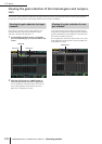

15 Graphic EQ and Parametric EQ
118 PM5D/PM5D-RH V2 / DSP5D Owner’s Manual Operating section
The PM5D provides twelve units of 31-band graphic EQ or 8-band parametric EQ (expandable to a
maximum of twenty units). This chapter explains how to use the graphic EQ and parametric EQ.
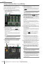
Patching the GEQ modules
The GEQ module built into the PM5D can be inserted into the insert-out/in of the desired channel. As an example, here’s how
to insert GEQ module into the STEREO A channel.
1
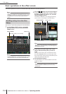
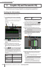
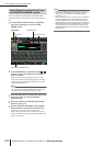
In the DISPLAY ACCESS section, repeatedly
press the [GEQ] key to access the GEQ PARAM
screen.
In this screen you can select a GEQ module, specify the
channel into which it will be inserted, and edit its
parameters.
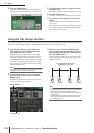
2
Click the / buttons at the left and right of
the MODULE box in the upper left of the
screen to select the GEQ module you want to
operate.
3
Click the GEQ/PEQ button located in the
upper middle of the screen, to switch between
31-band graphic EQ and 8-band parametric
EQ.
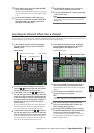
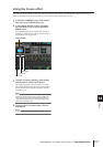
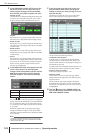
4
Click the / buttons at the left and right of
the INSERT box to select ST AL [INS] (STEREO
A L channel insert-in/out) as the channel into
which the GEQ module will be inserted, and
press the [ENTER] key (or click within the box).
You can choose one of the following insert
destinations.
If an insert destination is already assigned, a window
will appear when you click within the box, asking you
to confirm the change. Click the OK button to execute.
5
In the upper left of the screen, click the /
buttons at the left and right of the MODULE
box to select another GEQ module, and assign
it to ST AR [INS] (STEREO A R channel insert-
in) in the same way.
6
Click the GEQ ON/OFF button to turn it on.
Note
When you insert a GEQ module, the insert-in for the channel
will be enabled automatically.
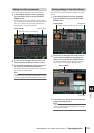
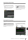
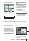
7
In the DISPLAY ACCESS section, repeatedly
press the OUTPUT [PATCH] key to access the
INSERT POINT screen.
8
If desired, change the insert point for the STE-
REO A channel into which you inserted the
GEQ module.
When you insert a GEQ module, the insert-in point for
that channel will be enabled automatically.
Note
• If you inserted a GEQ module into an input channel, repeat-
edly press the INPUT [PATCH] key to access the INSERT/
DIRECT OUT POINT screen (INPUT PATCH function), and
edit the settings in the same way.
• You can also insert a GEQ module into the desired chan-
nel’s insert-in/out by using the INSERT PATCH screen
(INPUT PATCH function and OUTPUT PATCH function).
15 Graphic EQ and Parametric EQ
INS CH 1–INS CH 48 Input channel 1–48 insert in/out
INS STIN1L–INS
STIN4R
ST IN channel 1–4 (L/R) insert in/
out
INS MIX 1–INS MIX 24 MIX channel 1–24 insert in/out
INS MTRX1–INS
MTRX8
MATRIX channel 1–8 insert in/out
INS ST AL/INS ST AR
STEREO A channel (L/R) insert
in/out
INS ST BL–INS ST BR STEREO B channel insert in/out
MODULE box GEQ/PEQ button
GEQ PARAM
INSERT box
INS MON L–INS MON C
(PM5D only)
MONITOR channel (L/R/C) insert
in/out
INSERT POINT
ON/OFF button Insert point