


MATRIX/ST function
266 PM5D/PM5D-RH V2 / DSP5D Owner’s Manual Reference section
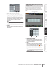
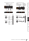
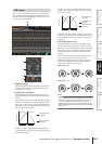
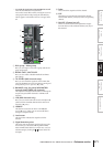
To change the position from which the signal is sent,
move the cursor to the vertical column for the desired
channel, and press the [ENTER] key, click, or turn the
[DATA] encoder. (The position of all signals sent from
that channel to all MATRIX buses will change
simultaneously.)
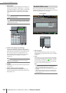
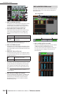
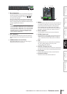
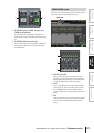
If the SEND POINT button is on, the send position for
all grid locations can be changed simultaneously. To do
so, hold down the [SHIFT] key and click the desired
grid. (Alternatively, move the cursor to the desired
grid; then hold down the [SHIFT] key and press the
[ENTER] key.) When the JOB SELECT window
appears, select one of the following choices, and click
the OK button.
ALL PRE FADER [ALL MIX ]
All grids will be set to PRE FADER.
ALL POST FADER [ALL MIX ]
All grids will be set to POST FADER.
ALL POST ON [ALL MIX ]
All grids will be set to POST ON.
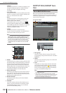
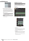
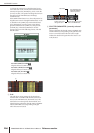
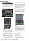
C Grid
The grid shows various settings for the signals sent
from the MIX or STEREO A/B channels (vertical col-
umns) to the MATRIX buses (horizontal rows). The
red lines shown in the upward, downward, left, and
right directions indicate the channel (MIX or STEREO
A/B) and MATRIX bus corresponding to the grid
where the cursor is located.
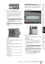
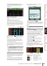
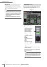
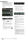
D SELECTED PARAMETER (currently selected
parameter)
This area indicates the channel (MIX or STEREO A/B)
and MATRIX bus corresponding to the grid where the
cursor is currently located. The four boxes at right
indicate the values for the grid where the cursor is cur-
rently located.
3
4
Send level
Pan (displayed if the
destination MATRIX
channel is paired)
Position from which
the signal is sent
On/off switch for the signal
sent to the MATRIX bus