


PM5D/PM5D-RH V2 / DSP5D Owner’s Manual Operating section 137
16
Remote control
❏ USER DEFINED KEYS
Operation of a User Defined key on the PM5D will be the
trigger for outputting a signal from the GPI OUT port.
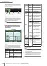
To edit the setting, click the button at the left to open
the GPI OUT PORT ASSIGN window; from the list, select
the User Defined key bank (A–D) and number (1–25), and
choose the trigger mode (how the trigger will operate when
the key is pressed). You can choose one of the following
trigger modes.
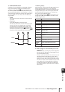
• LATCH
Alternate between active and inactive each time the key
is pressed.
• UNLATCH
Active only while the key remains pressed.
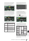
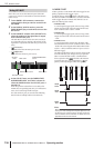
The following illustration shows how the output signal
from the GPI OUT port changes when you operate a
User Defined key in each of the trigger modes. (This
illustration shows operation when is selected as the
POLARITY of the GPI OUT port. If POLARITY is ,
the polarity of the output signal will be the opposite.)
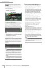
❏ TALLY (other)
Other operations on the PM5D will be the trigger for out-
putting a signal from the GPI OUT port. When the
corresponding operation is executed on the PM5D, a con-
trol signal will be output. This control signal will be held
until you defeat the above operation (or until that GPI
OUT port receives a different trigger).
To edit the settings, click the button at the left to open
the GPI OUT PORT ASSIGN window, and select one of
the following functions.
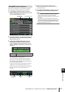
5
Make settings for other GPI OUT ports in the
same way.
With these settings, executing an operation assigned to
the GPI OUT port will output a control signal accord-
ing to the POLARITY setting.
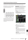
You can use the TEST buttons in the GPI OUT area to
check the operation of the GPI OUT ports. When a
TEST button is on, the corresponding GPI OUT port
will become active, and a control signal will be output.
The GPI OUT status column indicates the status of the
output signal of the corresponding port. The charac-
ters L/H indicate the Low or High level of the signal.
The background color is yellow when active, and gray
when inactive.
LATCH
UNLATCH
Function PM5D operation
NO ASSIGN No assignment
POWER ON The PM5D’s power is turned on
SOLO ON [SOLO] key is turned on
GPI IN 1
FUNCTION
The function assigned to GPI IN port 1
becomes active
GPI IN 2
FUNCTION
The function assigned to GPI IN port 2
becomes active
GPI IN 3
FUNCTION
The function assigned to GPI IN port 3
becomes active
GPI IN 4
FUNCTION
The function assigned to GPI IN port 4
becomes active
PREVIEW ON
SCENE MEMORY section [PREVIEW] key is
turned on
CUE ON
[INPUT ONLY]
Input channel [CUE] key is turned on
CUE ON
[DCA ONLY]
DCA [CUE] key is turned on
CUE ON
[OUTPUT
ONLY]
Output channel [CUE] key is turned on
CUE ON Any [CUE] key is turned on