


16 Remote control
136 PM5D/PM5D-RH V2 / DSP5D Owner’s Manual Operating section
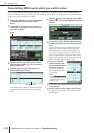
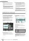
Here’s how you can use the GPI OUT ports of the GPI
connector to control an external device from the PM5D’s
faders or keys.
1
To the PM5D’s GPI connector, connect the
external device that you want to control from
the PM5D.
2
In the DISPLAY ACCESS section, press the
[MIDI/REMOTE] key several times to access the
GPI screen.
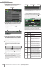
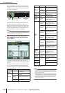
3
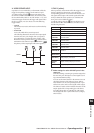
In the POLARITY column of the GPI OUT area,
select the polarity of the signal that is output
from each GPI OUT port.
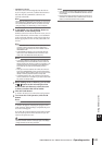
The POLARITY column of the GPI OUT area selects
one of the following two settings as the polarity of the
signal that is output when the GPI OUT port becomes
active.
• (Low active)
Grounded when the GPI OUT port is active.
• (High active)
Open when the GPI OUT port is active.
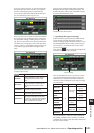
4
In the GPI OUT area, use the FADER START,
USER DEFINED KEYS, and TALLY columns to
select the PM5D function for GPI OUT ports 1
through 12.
When an operation selected here is executed on the
PM5D, the corresponding GPI OUT port will become
active, and a control signal will be output.
For each GPI OUT port you can select the following
three functions (multiple selections are allowed).
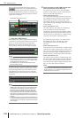
❏ FADER START
A fader operation on the PM5D will be the trigger for out-
putting a signal from the GPI OUT port.
To edit the setting, click the button at the left to open
the GPI OUT PORT ASSIGN window, and select the fader
mode (trigger detection method) and channel. You can
select the following fader modes.
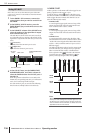
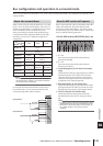
• FADER START
A control signal (trigger signal) 250 msec long will be
output when the fader of the selected channel moves
from –60 dB or below to above –60 dB.
• FADER STOP
A control signal (trigger signal) 250 msec long will be
output when the fader of the selected channel reaches
–∞ dB.
• FADER TALLY
A control signal will be output when the fader of the
selected channel moves from –60 dB or below to above
–60 dB. This control signal will be held until the fader
reaches –∞ dB (or until that GPI OUT port receives a
different trigger).
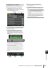
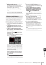
The following illustration shows how the output signal
from the GPI OUT port changes when you operate a
fader in each of the fader modes. (This illustration
shows operation when is selected as the POLAR-
ITY of the GPI OUT port. If POLARITY is , the
polarity of the output signal will be the opposite.)
Note
When the voltage is at High level, the output signal of the port
will be open. If the receiving device requires High level, it can
be taken from the +5 power supply pin. However in this case
there is a limitation on the current flow; for details, refer to the
Appendices at the end of this manual.
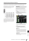
Using GPI OUT
TALLY columnFADER START column
GPI OUT
status
POLARITY column
TEST button
USER DEFINED KEYS
column
FADER
START
FADER
STOP
FADER
TALLY
➪
➠
➠
➠
➠
➪➪➪➪
250 msec
250 msec